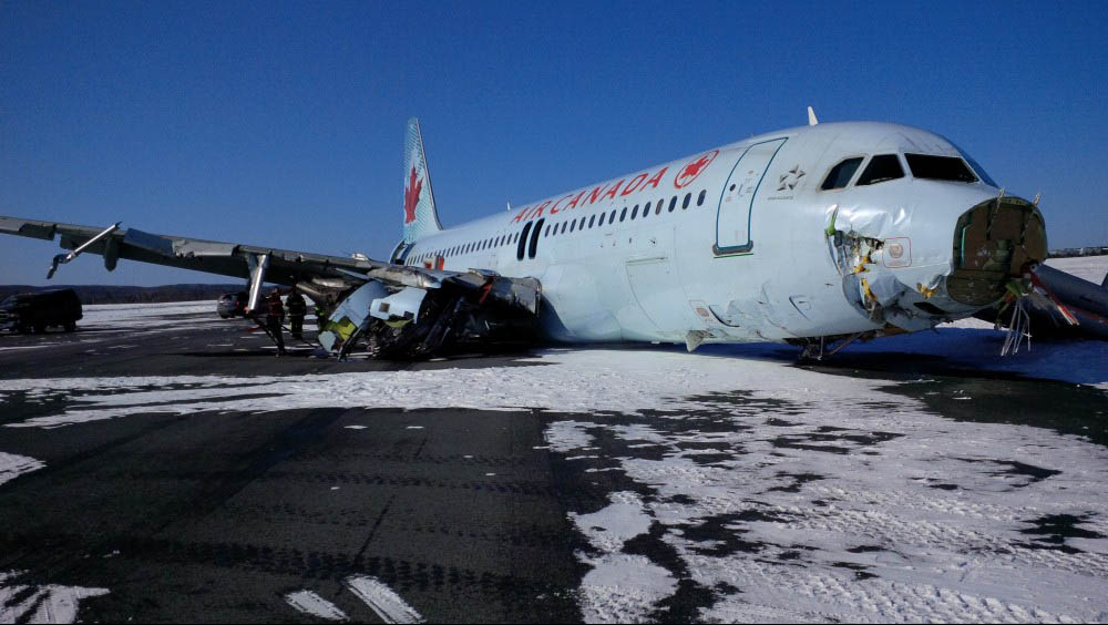
Transport Safety Board Canada photo
Do you ever wonder if there is a very obscure factoid out there that you have never been told about that is just lying in wait to bite you. That perhaps you are trying to do everything right, but because someone along the way left something out of your training and that something could cause you to destroy an airplane? I think that might describe these pilots who seem to have conducted themselves very well except for one small mistake and one big decision just seconds before they destroyed this airplane. But the alarming thing is I think that little factoid they were missing is something most of us may not know about either.
— James Albright

Updated:
2019-01-03
The little something has to do with Flight Path Angle (FPA) and how you use it on non-precision approaches. If you don't have an FPA or never heard of it, the same thing applies to using your autopilot's vertical speed function to descend from your FAF altitude down to the MDA or CDFA. If you don't understand that the FPA isn't drawn from the runway up, but from the airplane down, you need to do a little more study on the matter. I've tried to help in this article: Sitting Duck (Under). (If you don't fully understand FPA, you are a sitting duck for an automated duck under.)

1
Accident report
- Date: 29 March 2015
- Time: 00:30
- Type: Airbus A320-211
- Operator: Air Canada
- Registration: C-FTJP
- Fatalities: 0 of 5 crew, 0 of 133 passengers
- Aircraft fate: Damaged beyond repair
- Phase: Landing
- Airport (departure): Toronto-Pearson International Airport, ON (CYYZ), Canada
- Airport (arrival): Halifax-Stanfield International Airport, NS (CYHZ), Canada
2
Narrative
Aviation Investigation Report, A15H0002, Appendix A
The pilot flying made one small mistake when he began his descent from the FAF altitude: he started 0.2 nm early. That doesn't seem like much but it meant his airplane was on an angle that began (0.2)(6076) = 1,215 feet early. And that angle, if nothing else was changed, meant they would be 50 feet above the runway threshold 1,215 feet early too. But what the report calls "perturbations," such as the winds and turbulence, also pushed the airplane down in small doses, but from each of these pushes, the airplane resumed its FPA descent but from a lower altitude. The report misses another problem, however. Air Canada SOP had the crew adjust the FPA for the cold temperature as well, further lowering their glide path. So they were destined to make contact with the ground early if they did nothing to arrest the descent. And that leads to the very big mistake at the end. The visibility was poor and they continued the autopilot's descent below the MDA based on their dim view of the approach lights.
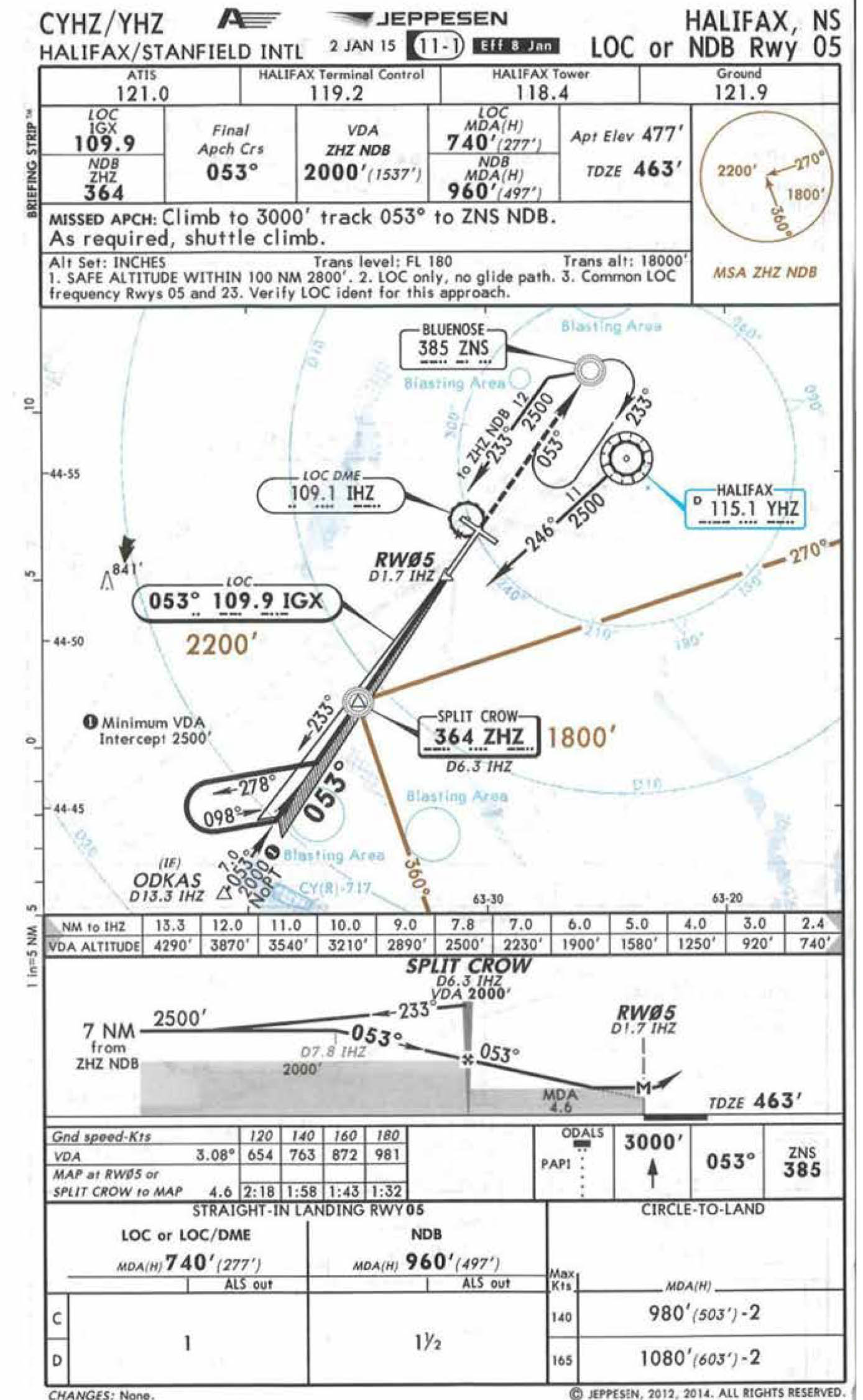
- Based on the weather forecast and the notices to airmen (NOTAMs), the flight crew determined that they would conduct the localizer (LOC) approach to Runway 05 in Halifax.
- While in cruise, the flight crew calculated the cold temperature corrections for the Split Crow final approach fix (FAF) crossing altitude, the minimum descent altitude (MDA), and the missed approach altitude. It was determined that the FAF crossing altitude would be 2200 feet above sea level (ASL), based on the published altitude of 2000 feet plus a cold temperature correction of 200 feet. The MDA was calculated at 813 feet ASL, based on the published MDA of 740 feet ASL plus a cold temperature correction of 23 feet, plus 50 feet added to the corrected MDA, as required by Air Canada’s Flight Operations Manual (FOM). The flight crew calculated a flight path angle (FPA) based on the temperature-corrected FAF. The calculation was based on the published vertical descent angle of −3.08° obtained from the Jeppesen approach chart and Air Canada’s Airbus A320 Quick Reference Handbook for a final calculated FPA of −3.5°.
Source: Aviation Investigation Report, A15H0002, ¶1.1
You might be wondering about the crew's decision to increase the FPA to 3.5° from the published 3.06°, in accordance with their manuals. The published FPA is based on the geometry of starting at 2,000 feet actual altitude and ending up 50 feet over the end of the runway, actual altitude:
Where:
- A is the desired descent angle
- a is the altitude to lose of 2,000 minus 463 plus a threshold crossing height of 50 equals 1,487 feet
- b is the distance to travel of 4.6 nm times 6,076 feet per nm
There may be a slight rounding error, but 3.06° appears correct.
The temperature correction means the airplane's altimetry begins 200 feet higher but ends up at the same point over the runway, so the math changes slightly:
But this all assumes that correction is constant from the FAF down to the runway; it isn't. Airbus and Air Canada have since given up on temperature correcting FPAs. For an explanation on why, see: Altimeter Temperature Correction / FPA.
- At about 2256, Air Canada dispatch provided the flight crew with weather updates and advised that, at 2230, an Air Canada flight had landed in CYHZ on Runway 05 after carrying out a missed approach due to insufficient visibility.
- The flight crew performed the go-around briefing and repeatedly reviewed the weather conditions at CYHZ. Based on the published runway conditions and the reported winds, and in accordance with the Quick Reference Handbook, they determined that the conditions were suitable for the aircraft to land.
- At 2321, about 2 minutes after the flight was cleared to descend to flight level 290, the flight crew carried out the approach briefing for a non-precision LOC approach to Runway 05, followed by the pre-descent checklist. These briefings included the corrected altitudes and amended FPA. The approach was to be coupled–selected with a manual landing.
- At 0016, the tower controller advised the flight crew of a special weather observation (SPECI) issued at 0013, which included the information that visibility was ½ sm in snow and drifting snow and that vertical visibility was 300 feet. Based on the improvement in visibility to the required minimum, the flight crew determined that they would continue and carry out an approach to Runway 05.
- At 0016, the terminal controller cleared AC624 to the intermediate fix ODKAS, 11.6 nautical miles (nm) from the runway, and cleared the flight to descend to 4000 feet ASL. AC624 was then cleared for the straight-in LOC approach via ODKAS and was advised that there was no change in weather and runway conditions from those previously reported. The flight crew continued the approach and, at about 0022, the landing lights were selected OFF, which turned the lamps off.
- Less than a minute later, AC624 contacted the tower to confirm that the runway lights were on setting 5. The tower controller, who was dealing with the snowplows on the runway and an aircraft taxiing for Runway 05, indicated that the lights were currently on setting 4, but would be on setting 5 in time for the landing.
- At 0023, AC624 leveled off at 3400 feet ASL about 12 nm from the threshold. Once level, with the autopilot (AP) on and the flight director lateral mode selected to LOC (localizer track mode), the flight crew began to configure the aircraft for the descent with AP 1 and autothrust still engaged. The flaps were set to Flaps 1.
- At 0024, approximately 11 nm from the runway threshold, the flaps were set to Flaps 2. The aircraft initiated a left turn to intercept, capture, and track the LOC. During this time, the flight crew noted that the ground could be seen when looking straight down as well as when looking off on a slight angle.
- At approximately 0026, about 8 nm from the runway threshold, the PF called for the landing gear to be extended and for the landing checks to be completed. The aircraft leveled off at 2200 feet ASL, the landing gear was extended, and the missed approach altitude was set. At about the same time, the tower controller requested that the snowplows vacate the runway.
- At 0027, about 6.7 nm from the runway threshold, the flaps were set to Flaps 3 followed by Flaps full. The aircraft was fully configured for landing before the FAF.
- About 2.7 nm from the FAF, using the vertical speed/flight path angle (V/S-FPA) knob on the flight control unit, the PF selected FPA mode; the aircraft was now being flown with the FPA selected to 0.0°.
- At 0027, the PM began the countdown for the distance to the FAF, indicating 0.5, 0.4, then 0.3 nm. At 0.3 nm from the FAF, the PF rotated the V/S-FPA knob to select −3.5°. The tower controller cleared AC624 to land; the runway lights remained at setting 4. The aircraft landing lights remained OFF, and the PM indicated that ground lighting was noted.
- The aircraft started to descend about 0.2 nm from the FAF. The aircraft crossed the FAF at 2170 feet indicated altitude
Source: Aviation Investigation Report, A15H0002, ¶1.1
The PF selected the descent 0.2 nm early, which comes to (0.2)(6076) = 1,215 feet. They crossed the FAF only 30 feet lower than their planned temperature corrected altitude of 2,200 feet.
As the aircraft descended, the actual flight path diverged from the desired profile as a result of wind variations. The divergence continued to increase throughout the approach. The airspeed was constant, and the vertical descent speed ranged between 700 and 800 feet per minute (fpm).
Source: Aviation Investigation Report, A15H0002, ¶1.1
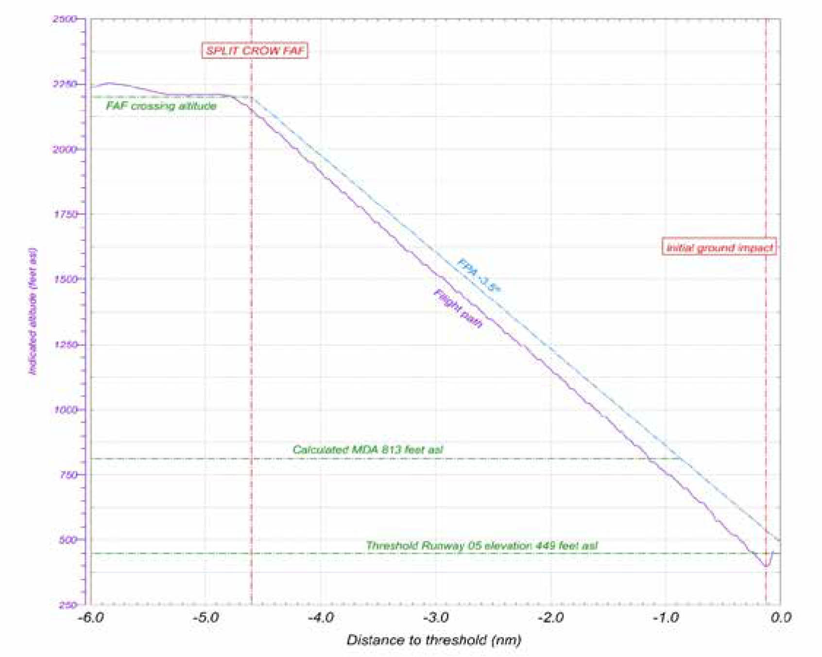
Aviation Investigation Report, A15H0002, fig. 1.
At 0029:27, a radio altimeter automated audio call (automated call) of “400” was made, indicating that the aircraft was 400 feet above the terrain. Almost immediately after this call, the aircraft crossed the calculated MDA at 1.2 nm from the threshold. The PM observed some approach lights and called, “Minimum, lights only,” when the aircraft was about 1.0 nm from the threshold. The PF immediately called, “Landing,” and began to observe some approach lights. By this time, the aircraft had crossed the published MDA (740 feet ASL) and was 0.3 nm farther back than the published distance. The autopilot remained engaged as the aircraft continued descending, and there was no reduction in the descent rate.
Source: Aviation Investigation Report, A15H0002, ¶1.1
While they began their descent (0.2)(6076) = 1,215 feet early, the steeper FPA and various changes in wind meant they ended up (0.3)(6076) = 1,883 feet early arriving at the MDA.
When the aircraft was about 0.7 nm from the threshold, the flight crew had a conversation in which both confirmed they could see some approach lights. At this time, the aircraft crossed over a lighted facility.
Source: Aviation Investigation Report, A15H0002, ¶1.1
When landing in very poor visibility, we expect to see the approach lights in front of us (or nearly in front of us if in a crosswind) and in a certain spot below us in the windshield. In this case, the added distance at the MDA lowered their look-down angle substantially. They should have been 277 / tan(3.06) = 5,182 feet from the runway at the MDA. The extra 1,883 feet of distance meant their actual angle was arctan(277 / (5182+1883)) = 2.2° -- about a degree lower. If our descent angle is off by a degree or two, we are unlikely to detect the difference. You expect to see the lights, and when you do, you expect they are in the correct position.
- At 0029:47, the landing lights were selected ON, followed in very quick succession by the PF disconnecting the autopilot an automated call of “100,” an automated call of “50,” and the PM instructing to pull up. AC624 then severed the electrical power line that ran perpendicular to the runway, causing a utility power outage at the airport terminal.
- About 1 second before initial ground impact, the PF advanced the thrust levers to the takeoff go-around detent and pulled the side-stick to the full nose-up position. One of the left main tires contacted an approach light located 861 feet from the runway threshold. At 0030:00, the aircraft’s main landing gear, aft lower fuselage, and left engine cowling struck the snow-covered ground on the south side of the embankment that sloped up toward the runway surface. The aircraft then struck the localizer antenna array and continued airborne before striking the ground twice more and then sliding along the runway. The aircraft came to rest about 1900 feet beyond the threshold. During these movements, the aircraft completely lost electrical power. The lights inside the cabin went off and the emergency lights activated automatically.
- At 0030:16, the tower controller activated the crash alarm.
- Although no evacuation order was given, passengers in rows 17 and 18 opened the 4 over-wing exits and began to exit the aircraft. The service director opened the forward left cabin (L1) door and directed the passengers to exit the aircraft. The slides at the cabin door and the over-wing exits deployed when the exits were opened.
Source: Aviation Investigation Report, A15H0002, ¶1.1
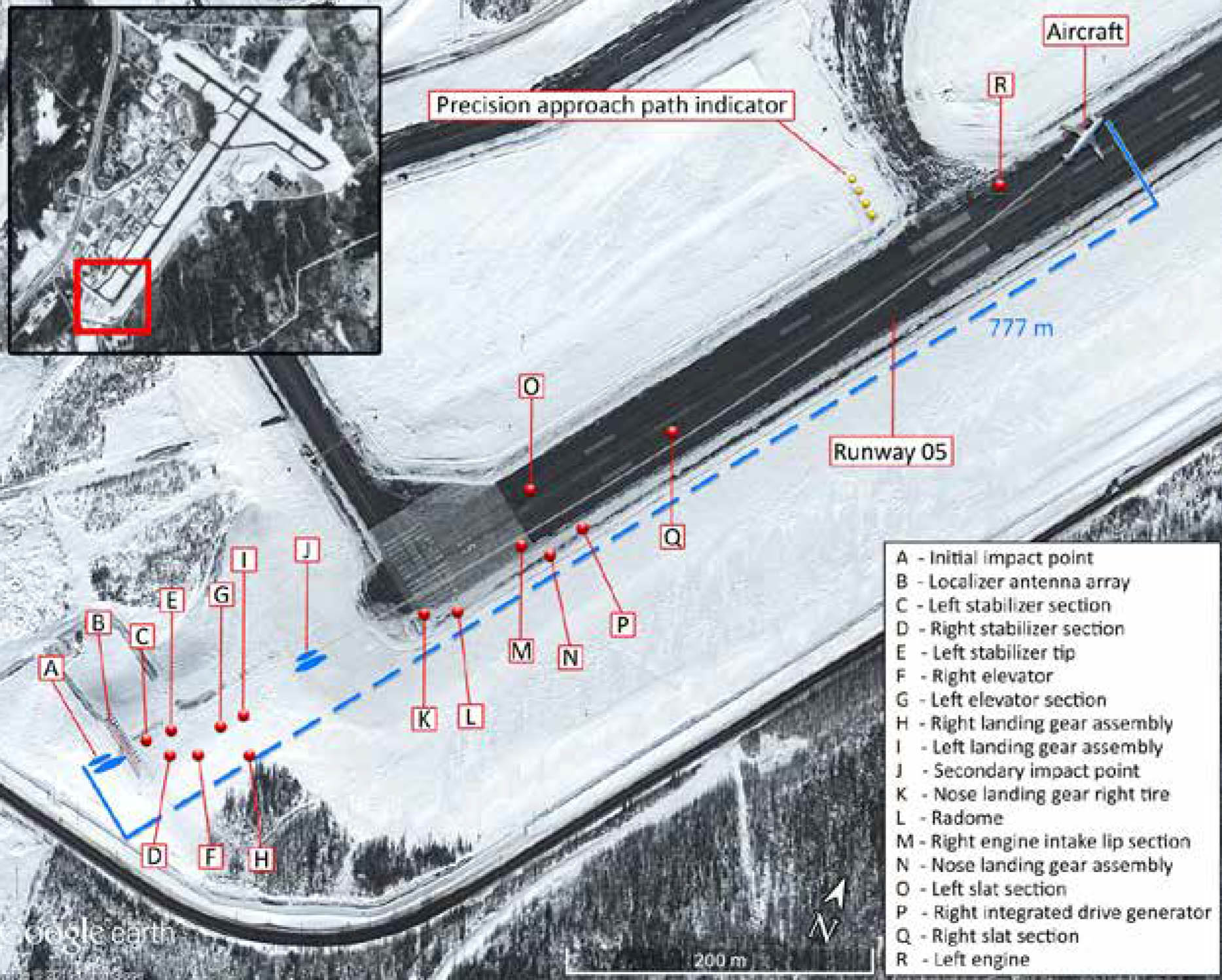
Aviation Investigation Report, A15H0002, fig. 7.
- The force of the initial impact crushed sections of the lower aft fuselage and caused the lower portion of both main landing gear to fracture and separate. Each separated portion of the main landing gear struck the corresponding horizontal stabilizer, causing large sections of the stabilizers, as well as the left elevator, to detach. These fragments were found along the debris field before the location of the second impact.
- After striking the ILS localizer antenna array, the aircraft continued airborne until the right engine and nose section struck the snow-covered ground. The right engine mounting pylon fractured; the separated engine was retained under the right wing. The nose landing gear collapsed rearward, and its lower portion fractured and separated.
- The aircraft then bounced before contacting the runway. The left engine completely detached from the wing and came to rest on the left side of the runway. The aircraft stopped on the left side of the runway in a slight nose-up and left-bank attitude, on an approximate heading of 025°M.
Source: Aviation Investigation Report, A15H0002, ¶1.12.1
3
Analysis
I was impressed with the professionalism of this crew and am worried that making a 0.2 nm mistake can end so badly. We often take away from these case studies important lessons that can seem rather obvious in hind sight. I think the lesson of this accident is to pay attention to the details and don't trust a new procedure, like a temperature corrected FPA, until it has been sufficiently tested.
- Operators under CARs Subparts 703, 704, and 705 may be permitted to conduct instrument approaches at 50% of published visibility values if they meet specified conditions and are authorized by an OPS Spec. Air Canada had the specified OPS Spec. According to its Quick Reference Handbook, LOC approaches inside Canada were authorized in the following conditions:
- Autopilot and flight director are used to the minimum descent altitude.
- For reported visibility below ½ sm (2600 feet), the aircraft is captain-flown.
- The published visibility for the CYHZ LOC approach on Runway 05 is 1 sm. Therefore, in accordance with Air Canada’s OPS Spec, the flight crew could carry out an approach with reported visibility of ½ sm.
Source: Aviation Investigation Report, A15H0002, ¶1.18.11
- The AOM and FCTM outline non-precision approaches and provide guidance on how to perform them. A coupled–selected approach is required for a LOC approach. When conducting a LOC approach, the lateral guidance is coupled to a LOC (autopilot directed by ground-based aids), and the vertical guidance is selected by the crew (autopilot directed by pilot-selected commands).
- The methods to fly a coupled–selected approach are as follows:
- AP [autopilot] should be engaged in LOC/FPA modes
- Use FD [flight director] referenced to the Flight Path Vector
- Select appropriate raw data on ND [navigation display] for monitoring tracking and descent
- Use A/THR [autothrust]
- Use managed speed
- When determining the flight path angle for the vertical guidance, pilots use the vertical descent angle (VDA) that is published on the applicable Jeppesen chart. The VDA defines the flight profile in which the aircraft will cross the runway threshold about 50 feet AGL.
- On a non-precision approach, once the flight crew has established visual contact with the runway environment and the autopilot has been disconnected, the PF manually flies the aircraft using visual cues to determine its lateral and vertical position relative to the runway. Air Canada training and pilot experience both reinforced the knowledge that there may be a need to make minor corrections to the flight path to ensure the aircraft maintains a stable approach and crosses the threshold at the correct height to ensure landing in the touchdown zone.
- According to the FCTM, for a coupled–selected approach, the FPA should be preset on the flight control unit. A smooth interception of the final approach path can be achieved by pulling the FPA selector knob when the aircraft is 0.3 nm before the FAF. The requirement to preset the FPA before pulling the selector knob is not specified in the AOM’s SOPs.
- During a non-precision approach, when the aircraft reaches the MDA, a PM is required to make a call of “Minimums” followed by either “No contact,” “Lights only,”71 or “Runway in sight.” The response by a PF is to call either “Go-around, flaps” or “Landing.” Air Canada does not provide any specific training on or definition of what “Lights only” entails.
- When a PM calls, “Lights only,” a PF expects that the PM has acquired visual references in order to continue with the approach. The typical response is for the PF to call, “Landing,” and to continue with the approach.
- In accordance with the AOM section 1.01.22, Autoflight limitations, at the MDA, when the required visual conditions are met to continue the approach, the autopilot must be disconnected.
- During the occurrence flight, the autopilot was not disconnected until the aircraft reached 484 feet ASL, about 23 seconds after passing the calculated MDA of 813 ASL, which did not conform with an aircraft flight manual limitation, CARs 602.07(a), or Air Canada’s SOPs.
Source: Aviation Investigation Report, A15H0002, ¶1.17.1.3
- A non-precision approach is an approach that uses lateral guidance but no vertical guidance. Therefore, before the MDA, flight crews may need to make minor flight path adjustments to correct for any vertical deviations from the intended descent profile. Transport Canada notes that:
- The need for a stabilized final approach during non-precision approaches (NPAs) has been recognized by the ICAO CFIT [controlled flight into terrain] Task Force as an aid to prevent CFIT accidents.
- The stabilized constant descent angle (SCDA) technique involves intercepting and maintaining a constant angular descent profile from the FAF to a reference datum above the runway threshold (typically 50 feet). The descent is therefore flown at a constant angle and a constant rate of descent, requiring no configuration change. When using the SCDA technique, upon reaching the MDA, the flight crew decides either to continue on the constant angle to land if the required visual references are in sight, or to execute a missed approach if visual conditions are not imminent.
- The SCDA technique requires no specific aircraft equipment other than that specified by the title of the non-precision approach procedure. Pilots can fly suitable non-precision approaches with a SCDA using basic piloting techniques. The benefits of the SCDA technique have been demonstrated and validated by TC and several international organizations.
- According to Transport Canada Aeronautical Information Manual (TC AIM), the “SCDA is considered a form of ICAO’s continuous descent final approach (CDFA). In the interest of respecting terminology already in use in the Canadian civil aviation industry and standardization with NAV CANADA charting, the [SCDA] terminology has been adopted.”
Source: Aviation Investigation Report, A15H0002, ¶1.18.1
Aviation Investigation Report, A15H0002, fig. 15.
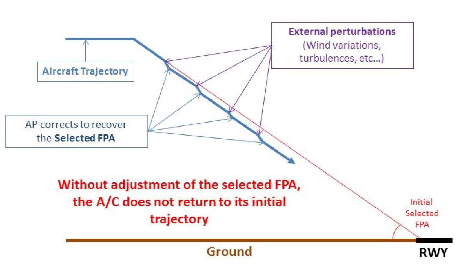
- The Airbus FPA guidance mode is a selected vertical mode that guides the aircraft to fly an FPA target and that can be used for approach. The FPA is the angle between horizontal and the total velocity vector of the aircraft. Therefore, the FPA guidance mode does not provide fixed vertical guidance with any reference to a ground-based aid, such as glide slope or ILS approach.
- When flying with the FPA guidance mode, external perturbations, such as wind variations or turbulence, can cause the aircraft to move away from the selected FPA initial approach path. If these perturbations result in momentary changes to the aircraft’s vertical trajectory, then the autopilot will recover the selected FPA, effectively paralleling the initial trajectory.
- If the perturbations cause the aircraft to move below the initial approach path, then once the autopilot captures the selected FPA, the aircraft will continue to descend, but on a flight path that is below and parallel to the initial approach path. If these perturbations continue throughout the descent and the flight crew makes no adjustments to recover the initial approach path, then the altitude discrepancy between the initial and actual flight paths will continue to increase, resulting in the aircraft flying below the published approach vertical profile. This actual flight path will result in a low indication on the airport’s approach slope indicators. A go-around must be initiated unless the flight crew estimates that only small corrections are necessary to rectify minor deviations from stabilized conditions.
- The Airbus FCOM does not offer guidance on how to make adjustments to the FPA; for example, it does not indicate how large the adjustment should be or for how long the adjustment should be made in order to return an aircraft to the selected flight path. For a flight in FPA guidance mode, Air Canada’s practice was that, once the aircraft was past the FAF, the flight crews were not required to monitor the aircraft’s altitude and distance from the threshold, nor to make any adjustments to the FPA.
- According to Airbus SOPs, the FPA guidance mode should be selected (by selecting TRK/FPA or “bird” with the HDG V/S-TRK FPA pushbutton) and the descent angle set before 0.3 nm from the final descent point. At 0.3 nm from the final descent point, the flight crew should pull the VS/FPA knob to begin the descent.
- Air Canada’s practice was that, once the aircraft was in level flight before the FAF, the pilot pulled the V/S-FPA knob and selected the angle to 0.0, then flew the aircraft in that mode. At 0.3 nm from the FAF, the pilot then selected the appropriate angle for descent.
Source: Aviation Investigation Report, A15H0002, ¶1.18.2
- Pressure altimeters are calibrated to indicate true altitude under international standard atmosphere (ISA) conditions (referred to as a standard day). Any deviation from a standard day results in an erroneous reading on the altimeter. If the temperature is lower than ISA, the true altitude will be lower than the indicated altitude. Although there is no regulatory requirement to do so, temperature corrections for cold weather should be added to the published altitudes on instrument approach charts to ensure obstacle clearance, since the altimeter displays will read incorrectly in these temperatures.
- The parameters computed by the Airbus air data inertial reference unit are barometric and ISA-referenced. When the atmosphere differs from ISA conditions, the altitude and FPA computed by the air data inertial reference unit, and the associated indications on the PFDs (altitude, vertical deviation, etc.), are inaccurate. Therefore, an aircraft conducting a non-precision approach must be operated at an indicated altitude that is corrected to compensate for the effect of cold temperature, and the FPA, which is the published vertical descent angle, must be adjusted to compensate for the temperature-corrected indicated altitude.
- In 2009, while working with Air Canada, TC identified a discrepancy involving all Airbus A320, A330, and A340 series aircraft when a non-precision approach was carried out in cold temperatures. When the cold temperature corrections were applied to the FAF altitude and the aircraft was flown with the FPA selected to the published vertical descent angle, the aircraft’s position did not accurately correspond to the published distances and altitude. Since the Airbus FCOM did not include any applicable procedures, TC required Air Canada to work with Airbus to develop a procedure so that, when a cold temperature correction is applied to a FAF altitude, the FPA can be adjusted to compensate for the corrected altitude.
- In April 2010, Airbus published a Temporary Revision to the FCOM Standard Operating Procedures, Non-Precision Approaches. Although this revision, which introduced an FPA correction chart for cold weather operation, provided additional guidance, it did not take into account Air Canada’s procedure for rounding up the correction altitudes. Therefore, Air Canada decided to develop its own procedures for adjusting the FPA when cold temperature corrections had been applied to the FAF altitude. This method was accepted by TC, and, in early 2011, Air Canada’s Airbus A320 Quick Reference Handbook was revised to include the FPA and chart of approach altitude corrections for cold temperatures.86 The chart was designed to identify the applicable altitude correction (in 100-foot increments) to be added to the FAF and the degree correction to be added to the FPA based on the approach altitude height above the aerodrome and the temperature in degrees Celsius. The Quick Reference Handbook also includes a chart for the cold temperature corrections for the MDA. The investigation determined that the FPA calculated by the flight crew was in accordance with the Quick Reference Handbook.
Source: Aviation Investigation Report, A15H0002, ¶1.18.3
- The stabilized constant descent angle technique involves flying a constant descent angle so that the aircraft will cross the runway threshold at the correct height. This angle corresponds to the published vertical descent angle (VDA), which defines the flight profile in which the aircraft will cross the runway threshold about 50 feet above ground level (AGL) to ensure landing within the touchdown zone.
- One way a pilot can verify the aircraft is on a flight profile consistent with the VDA is to monitor the aircraft’s altitude and distance from the threshold. Since 2014, both NAV CANADA and Jeppesen have included a distance/altitude table on selected charts.
- Air Canada’s standard operating procedure and historical practice when flying in flight path angle (FPA) guidance mode was that once the aircraft was past the final approach fix (FAF), the flight crews were not required to monitor the aircraft’s altitude and distance from the threshold or to make any adjustments to the FPA. This practice was not in accordance with Air Canada’s and Airbus’s flight crew operating manuals (FCOM).
- Although TC reviewed and approved Air Canada’s AOM and the SOPs, it had not identified the discrepancy between the Air Canada SOPs and the Airbus FCOM regarding the requirement to monitor the aircraft’s vertical flight path beyond the final approach fix when the FPA guidance mode is engaged.
- Flight crews select an FPA that corresponds to the published VDA, and the aircraft’s autopilot system maintains the selected FPA. However, in the FPA guidance mode, the aircraft is susceptible to perturbations which, if not compensated for by manual corrections to the FPA, could alter the flight profile. If such perturbations are present during an approach and flight crews are following Air Canada’s practice, flight crews could be unaware of their effect on the selected flight path.
- If the actual flight path deviates from the selected flight path as defined by the published VDA, flight crews may have to make adjustments to the flight profile in order to safely continue on with the visual portion of the approach to touchdown. During a stable approach, these adjustments could be minor and may not be sufficient to result in a deviation from stable approach criteria.
Source: Aviation Investigation Report, A15H0002, ¶2.2
An Air Canada Boeing 767 was damaged after landing at Halifax on March 8, 1996. The aircraft suffered a tail strike because of an unusually high pitch attitude. The accident report says: "Visual illusions during the approach caused both crew members to believe that the aircraft was higher than it actually was, leading to an unwarranted thrust reduction 10 seconds before touchdown." The accident report noted that the runway's slope is 0.77 percent up for the first one-fourth of its length and then goes down at 0.5 percent to the halfway point, after which point it is level. It is possible that Air Canada 624's crew was also faced with the same visual illusion.
4
Cause
I think the accident report got this mostly right and I think that should be alarming to most pilots. After you've shot your 10th or 20th landing to minimums, you start to think it isn't that big a deal. And perhaps with an ILS and a full set of approach lights it isn't. But a non-precision approach changes everything. If you have a HUD that gives you an FPA and an FPV (Flight Path Vector) you owe it to yourself to get into the habit of looking at them for every landing. That way when the weather is poor and a visual illusion is about to bite you, you will figure that out before it does. More about how to land with the FPA/FPV combination: Sitting Duck.
- Air Canada’s standard operating procedure (SOP) and practice when flying in flight path angle guidance mode was that, once the aircraft was past the final approach fix, the flight crews were not required to monitor the aircraft’s altitude and distance from the threshold or to make any adjustments to the flight path angle. This practice was not in accordance with the flight crew operating manuals of Air Canada or Airbus.
- As per Air Canada’s practice, once the flight path angle was selected and the aircraft began to descend, the flight crew did not monitor the altitude and distance from the threshold, nor did they make any adjustments to the flight path angle.
- The flight crew did not notice that the aircraft had drifted below and diverged from the planned vertical descent angle flight profile, nor were they aware that the aircraft had crossed the minimum descent altitude further back from the threshold.
- Considering the challenging conditions to acquire and maintain the visual cues, it is likely the flight crew delayed disconnecting the autopilot until beyond the minimum descent altitude because of their reliance on the autopilot system.
- The limited number of visual cues and the short time that they were available to the flight crew, combined with potential visual illusions and the reduced brightness of the approach and runway lights, diminished the flight crew’s ability to detect that the aircraft’s approach path was taking it short of the runway.
- The flight crew’s recognition that the aircraft was too low during the approach would have been delayed because of plan continuation bias.
Source: Aviation Investigation Report, A15H0002, ¶3.1
There were many other factors listed in the report, these are just the pilot related factors.
References
(Source material)
Aviation Investigation Report, A15H0002, Collision with terrain, Air Canada, Airbus Industrie A320-211, C-FTJP, Halifax/Stanfield International Airport, Halifax, Nova Scotia, 29 March 2015.