In Air Force instrument instructor school, we learn that the relationship of 60 nautical miles to 1 nautical mile holds magical meaning in the world of flight. See 60 to 1 for a story about how the mathematics was presented to a crowd of pilots normally allergic to all things arithmetic. See TLAR for a story of a child of "That Looks About Right" learning a new set of tricks.
— James Albright

Updated:
2020-12-17
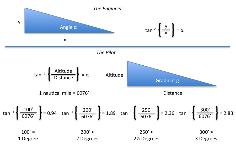
The problem is that the math taught in the instrument instructor school doesn't really hold up. (See Rules of Thumb for the math behind many of these rules of thumb.) As with many things aviation, the pilot doesn't need perfection, the pilot needs a way to achieve precision. If a little mathematical slight of hand is needed, so be it.
As you can see in the figure here, the math isn't that complicated and all you need know is that "almost equals" symbol (≈) works because the difference between 2.83 and 3° is imperceptible on a pilot's instruments. Here then are some math derived from this an other relationships.
4 — Circle from the opposite runway
1
Arc around a point

To fly an arc around a point, use a bank angle equal to the turn radius times 30 divided by the arc length.
Example
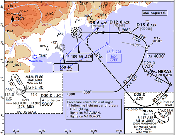
VOR B Rwy 22L/R, Planview, from Jeppesen Airway Manual, page LFMN 13-2, 19 Jun 2015.
Many modern aircraft have Flight Management Systems that know how to fly an arc around a VOR and you might go an entire career without this skill. Or maybe not. In 2002 I was in the right seat of a Challenger 604 and noted the approach was not in the database and the pilot would have to fly it manually. He looked at the arc and said they would never make him do that. Of course they did. "I don't know how to do that," he said. I flew it from the right seat, explaining as I did. He said it was like flying in the days of the early air mail delivery service. It isn't that hard, see Arcs for my notes from back in 1979.
You can fly the arc by picking a heading that places the bearing pointer on your inside wing tip and then adjusting the heading to bracket the bearing pointer plus 10°, minus 5° of the wing tip. Or you can fly the exact bank angle. In this case, flying at 150 knots (2.5 nm/min) we know we have a turn radius of (2.5)2/9 = 0.69 nm. We then can find the precise bank angle: (0.69)(30)/(20) = 1 degree. Not much, of course.
Proof
We already figured a formula to compute radius from bank angle in step 15 of Turn Radius. For the sake of clarity, we'll call the radius resulting from the velocity and bank angle combination the ARCRADIUS:
We can solve for the bank angle, θ, with a little algebra:
We also know that our turn radius, TR, is equal to our velocity squared divided by 9. Substituting:
For the purposes of our math here, 2 is close enough to 2.11, so . . .
So, by definition:
For small angles we can say the tan(θ) = θ in radians, but we are dealing with degrees. Therefore:
Substituting:
Let's call π ≈ 3. Then it follows . . .
A little math follows . . .
And finally we come up it the AFIIC rule of thumb. . .
This works pretty well until the arc radius gets smaller than 5 or so.
So for our LFMN (Nice, France) example with the 20 DME arc radius off of AZR flying at 150 knots with a turn radius of 0.69 nm, the two formulas produce the following:
The AFIIC rule of thumb is close:
So in our Nice, France example it was hardly any bank at all. What about arc that is just 5 DME?
The AFIIC rule of thumb is off a little bit:
Not really a big deal, plus or minus a degree is pretty good.
2
Arc distance
The distance traveled along an arc is equal to the arc radius times the arc angle divided by 60.
Example
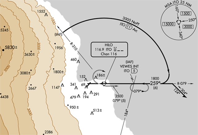
PHTO VOR/DME Runway 26 Planview, from FAA AL-756, 4 Feb 2016.
In the arc approach into Runway 26 at Hilo (PHTO), for example, you can be cleared for the approach from 5,000 feet at the IAF. You need to descend to 1,800 feet by the time you roll out on final. Is that a speed brakes, stomach churning dive? Or is it a gentle, tropical descent, hardly noticeable from the paying seats? With the aid of this rule of thumb you know that you will have to travel from the 079° radial though 360° (79°) and then from the 360° radial to 310° for another 50°. So you are crossing 79 + 50 = 129°. The rule of thumb tells us we have (11) (129) / 60 = 24 miles to lose 3,200 feet. No big deal.
Proof
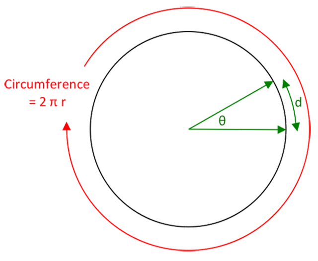
The AFIIC rule of thumb is this: the distance traveled along an arc is equal to the arc radius times the arc angle divided by 60.
But is that true?
We know, by definition:
Circle's angular circumference = 360°
Therefore:
The exact answer is the arc radius times the angle divided by 57.30. The AFIIC answer is certainly easier to remember and compute and is only in error by 4.5%. We should, therefore, adopt it:
Engineer Al Klayton offers an even better way to look at this, provided you do the math in radians (as explained here: Rules of Thumb / Radians).
θRadians = S/R, so:
S = R (θRadians) which in DME arc language is:
S(DME arc length) = R(DME arc radius) x θ(arc angle in degs) x π/180(conversion from degs to radians)
So if we approximate π as 3 we get:
DME arc length = DME arc radius x DME arc angle/60
3
Circle from a 90° offset
To provide circling offset when approaching a runway at 90°, overfly the runway and time for 20 seconds (Category D) or 15 seconds (Category C) before turning downwind.
Example
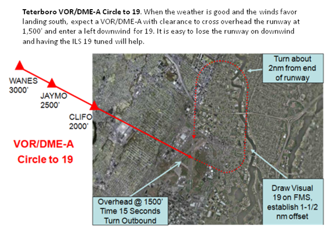
Teterboro VOR/DME Circle to Runway 19
In the old days, when the weather was good and Teterboro was landing on Runway 19, the only approach choice was to circle from a course almost 90° to the landing runway.
In our GV we would fly this circling approach at 120 knots for a turn radius of 0.44 nm. (Explained next.) Running the math you end up with an offset time of 13 seconds. Our rule of thumb is for 15 seconds which ends up being perfect, given the turn to downwind is slightly more than 90°.
Proof
Many pilots use a 15 second offset when approaching a circling runway from a perpendicular heading. They start timing when overhead the runway, 15 seconds later they roll onto downwind. Sometimes it works, sometimes it doesn't. As is turns out, 15 seconds is a compromised number. The real number is slightly lower for an airplane circling at 120 knots, slightly higher for one at 150 knots. Does "slightly higher" or "slightly lower" matter? Perhaps not. But if your ground speed is affected by winds or pressure altitude, it would be nice to know how to adjust, eh?
Circling 90° to runway
You will need to time overhead the runway and then you need to turn to the correct downwind heading, adjusted for the winds.
r = 0.69 nm
Time to delay downwind turn after crossing runway at typical Category D speeds:
For typical Category C speeds, 120 knots, r = 0.44 nm, t = 13 seconds
Of course these times do not include the roll in and roll out of the turn, both of which increase the turn radius. Despite this, it may be a good technique to round up to the nearest 5 second increment.
To provide circling offset when approaching a runway at 90°, overfly the runway and time for 20 seconds (Category D) or 15 seconds (Category C) before turning downwind.
4
Circle from the opposite runway
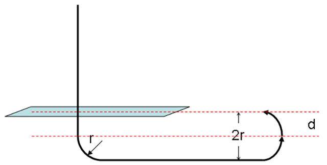
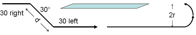
To provide circling offset when approaching from the opposite runway, turn 30° away from heading while starting your stop watch, time for 66 seconds (Category D) or 53 seconds (Category C), and then turn to parallel the runway on downwind.
Example
Circling from opposite runway
A Challenger 604 typically circles at 150 knots. Let's say we are flying to Runway 11 with instructions to circle to Runway 29. The rule of thumb says turn 30°, time for 66 seconds, turn back to the original heading for a downwind, and then turn final at the appropriate time. Your downwind displacement should make the base turn work out perfectly.
Proof
You can use a 30° or 45° offset, your choice, but it is important to get to that heading using a standard rate turn to make the timing work. The objective, of course, it to establish a downwind offset. Once you've done that, you need to adjust that heading for wind. I use 30°, reasoning that you don't need 45° and it is too easy to lose sight with that angular offset.
The distance traveled “d” on that 30 degree leg would be equal to twice the turn radius divided by the sine of 30 degrees. Once again everything hinges on turn radius.
The distance to travel a 30° offset leg:
The time to fly that leg at typical Category D speeds:
For typical Category C speeds, r = 0.44, d = 1.76, t = 53 seconds.
5
Descent gradient
Flight levels divided by nautical miles equals gradient.
Nautical miles per minute times descent angle times 100 gives vertical velocity in feet per minute.
Example
Gradient example
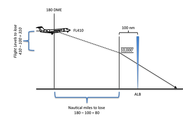
You are at FL 410, flying to Boston, and ATC gives you direct ALB with 435 nm to go and you have absolutely nothing to do for the next 48 minutes. But when you get to 180 DME they throw in a curve ball: "Cross 100 miles west of Albany at 10,000 feet." We know the descent gradient is equal to the flight levels to lose divided by the nautical miles to go, but the math
isn't so straight forward.
We want to do this without a calculator, slide rule, or Stephen Hawking in the jump seat. Well, 8 is a factor of 32 — it divides easily — and if we can make the gradient with 320 flight levels to lose we can certainly do it with only 310 flight levels. And that makes life for us as pilots easier:
If we achieve a 4° descent gradient, we will make it to our restriction with room to spare. So leave the boards stowed for now and see what kind of VVI we've got with the power levers at idle.
Proof
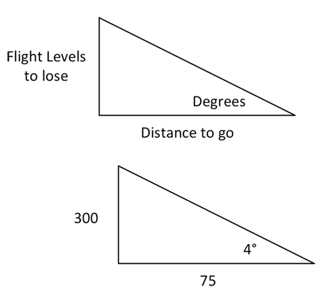
60-to-1 Descent Gradient
The basic 60-to-1 theory tells us that 1 nautical mile horizontally requires 100 feet vertically at a 1° gradient. A flight level is equal to 100 feet, so the rule follows naturally. If you are at FL 450, for example, and center directs you to descend to and maintain 15,000 feet before crossing a fix that you are 75 nm away from, your descent gradient will be:
But there is some poetic license here, since an airplane climbing or descending isn't behaving as if on an arc of a circle. The real answer has more to do with trigonometry:
In the case of our example, the actual gradient is:
So the theory is off by 6 percent, not too bad.
6
Glide path on final
Nautical miles per hour times ten divided by two gives a good three degree glide path VVI.
Or: Groundspeed times 5 equals VVI
Or: Half your groundspeed, add a zero, equals VVI
Example
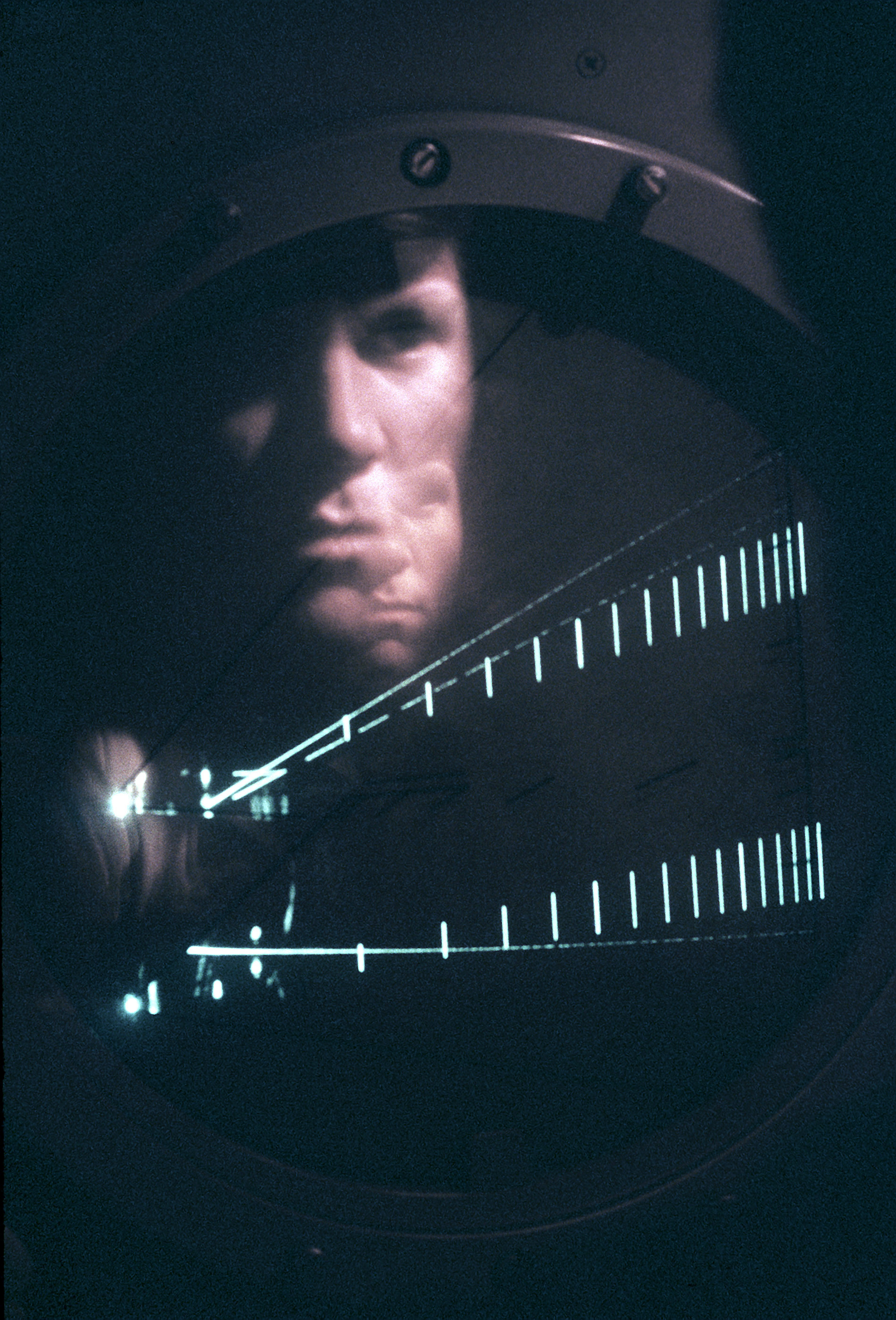
SRA James Calkins, PAR controller, Scott AFB, 1980 (USAF photo)
Let's say your are flying an ILS without a flight director (or find yourself flying a PAR approach), the glide path is based on a 3° angle, and you need to know what your target VVI should be on glide path. If your approach speed is 130 and you have a 10 knot headwind, you assume you will have a ground speed of 120 knots. Of course this may not be true at higher elevations where your KTAS will be higher, impacting your ground speed and you may want to adjust. If you have a ground speed readout, use that. But the math is pretty easy:
Doing the math:
If you want to know more about PAR approaches: Precision Approach Radar (PAR).
Proof
Descent VVI
The AFIIC rule for computing a target vertical velocity on final approach can be written thusly:
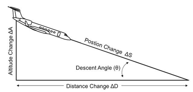
The mathematically pure answer is fairly easy, as long as we keep the units consistent. An engineer refers to a change in a quantity with the Greek symbol delta, Δ. A change in altitude, A, for example, can be found by subtracting the first altitude, A1, from the second altitude, A2. The engineer cites this as ΔA = A1 - A2. The airplane's position change along its route of flight, ΔS, is nothing more than the velocity. The math for our Descent VVI is fairly easy, as long as we keep the units straight:
For example, let's say you are flying down a 3° glide path at 120 knots, which comes to 2 nm/min. We want the end result in ft/min; that comes to 120 (nm/hr) (6076) (ft/nm) (1/60) (hr/min) = 12,152 ft/min. The rate of altitude change is:
Now we certainly can't fine tune our vertical descent to that degree, 634 ft/min. If we permit ourselves some approximation, we can derive an easier to use rule of thumb.
Therefore . . .
Also . . .
Combining . . .
And . . .
Now looking at the VVI side of things, we need to be careful about the units. Since VVI is presented in feet per minute, we have to convert the change in altitude, ΔA, into feet. There are 6,076 feet in a nautical mile, but we are in the business of approximating for these rules of thumb, so we'll use 6,000:
We can substitute our earlier value for Δt . . .
And through the magic of algebra . . .
Now, for small angles, the math wizards tell us that the sin( θ ) = θ expressed in radians. We can convert θ to radians knowing 2π radians = 360 degrees.
Simplifying:
It is true that π = 3.1416... and so on. But let's call it 3:
And now we have a rule of thumb worthy of AFIIC:
The AFIIC rule of thumb comes to (2 nm/min) (3 degrees) (100) = 600 fpm (just 5% in error).
7
Holding pattern teardrop angle
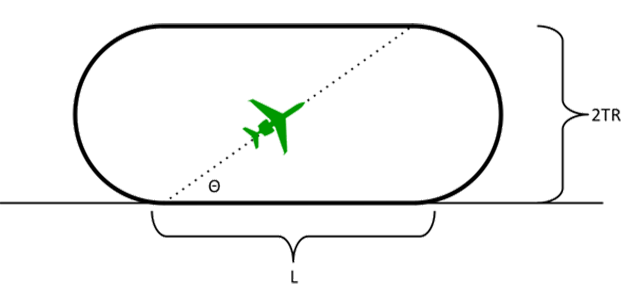
A holding pattern teardrop angle of 120 times the turn radius divided by leg length will provide an on course roll out, no wind.
Example
Holding pattern teardrop angle
The AFIIC rule is to multiply the airplane's turning radius by 120 and dividing that by the leg distance of the holding pattern. If, for example, you had a turning radius, TR, of a half mile and the leg distance, L, was 10 miles, your best, no-wind entry angle would be (120) (0.5) / (10) = 6 degrees. This works. But can we prove it?
Example
The trigonometry is straight forward (from the drawing):
We've already seen that TR is equal to the ground speed, in nautical miles per minute, squared, divided by 9. Substituting:
None of this resembles the AFIIC rule of thumb:
Running through several examples, we see the AFIIC rule of thumb is never off by more than 6% for most typical holding pattern lengths and speeds you would see in a holding pattern. As 120 knots (2 nm/min), for example, the AFIIC rule of thumb says you would need 10.6° for a 5 nm leg, 5.3° for a 10 nm leg, 3.5° for a 15 nm leg, and 2.6° for a 20 nm leg. The actual answers are 10.0°, 5.0°, 3.4°, and 2.5°.
By substituting typical holding pattern speeds for 120 knots (2 nm/min), 150 knots (2.5 nm/hr), and 180 knots (3 nm/hr) we can come up with three more useful formulas.
At 120 knots:
At 150 knots:
At 180 knots:
Looking for a simpler way to present this:
This is easier to compute than the AFIIC answer, has just as little to do with the actual math, and is as accurate, so we adopt it . . .
8
Top of descent
Start descent at three times your altitude to lose in thousands of feet to achieve a three degree gradient.
Example
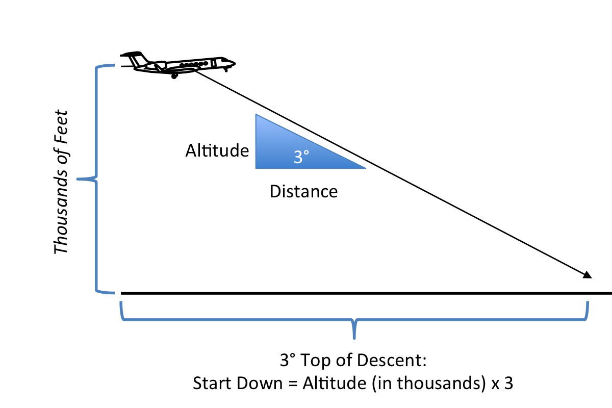
3° Top of Descent
Let's say you are cruising at FL 410 and are planning a descent into an airport that is just over 1,000 feet MSL elevation. So you have 40 thousand feet to lose. When should you start your descent?
Proof
If you multiply your altitude in thousands of feet by three, you will arrive at the ideal distance to start your descent and end up with about a three degree descent gradient. We've been doing that for years. The 60-to-1 mavens will have you believe this is an offshoot of the earlier flight levels to lose technique:
If you do the math, that would mean:
Top Descent trigonometry
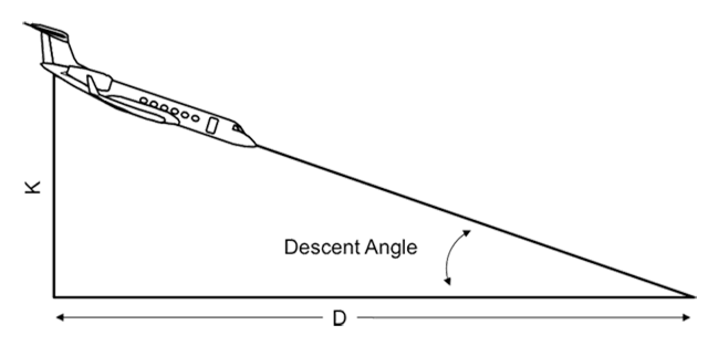
That works, but that isn't the "school solution." We can verify the technique using trigonometry. We will use K to represent the altitude in thousands of feet and D for the distance in nautical miles. Of course that means the formulas will require two conversion factors:
For a 3° angle, tan(θ) = 0.0524 and the math works out to:
That is an error of less than 5% from our time-tested rule of thumb.
Start descent at four times your altitude to lose in thousands of feet to achieve a 2.5 degree gradient.
Example
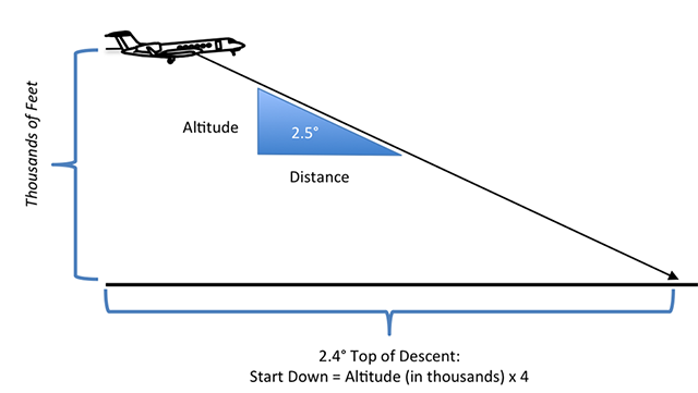
2.5° Top of Descent
Let's say you are cruising at FL 410 and are planning a descent into an airport that is just over 1,000 feet MSL elevation. So you have 40 thousand feet to lose. If you want a gentle 2.5 descent, when should you start your descent?
Proof
If you multiply your altitude in thousands of feet by four, you will arrive at the ideal distance to start your descent and end up with about a 2.5 degree descent gradient. The 60-to-1 mavens will have you believe this is an offshoot of the earlier flight levels to lose technique:
If you do the math, that would mean:
Top Descent trigonometry
That works, but that isn't the "school solution." We can verify the technique using trigonometry. We will use K to represent the altitude in thousands of feet and D for the distance in nautical miles. Of course that means the formulas will require two conversion factors:
For a 2.5° angle, tan(θ) = 0.0437 and the math works out to:
That is an error of less than 6% from our time-tested rule of thumb.
9
Turn radius
At 25 degrees of bank, turn radius is equal to nautical miles per minute squared, divided by nine.
Note: you can say "divided by ten" and be close enough.
Example
Circle 90° to runway
Let's say you want to determine the minimum runway displacement for a downwind when circling to an unfamiliar runway. Knowing your turn radius will make this easy.
If you were to shoot this approach at 150 knots the math isn't so easy. So let's try 120 knots first. Then the math comes to:
or about a half mile, so your turn diameter is about a mile.
Now let's try 180 knots:
That's a mile, so your turn diameter is about two miles.
So if you are circling at 150 knots, split the difference and you come up with a diameter of 1-1/2 miles. (If you did the math at 150 knots it would have come to 1.39 miles, so we are pretty close.
Proof
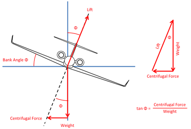
Turning flight
- In coordinated turning flight, we know the centrifugal force pulling the airplane away from the turn is equal to the mass of the airplane times the acceleration force.
- We also know that the aerodynamic force, lift, resolves to two components that oppose the weight vertically and the centrifugal force horizontally.
- The three forces, lift, weight, and centrifugal force can be drawn as a triangle with the acute angle equal to the bank angle θ of the airplane.
- The tangent of the bank angle θ is equal to the centrifugal force CF divided by the weight W.
- The weight of the airplane W is equal to its mass m times the gravitational constant g
- Substituting:
- By definition acceleration a is equal to the velocity divided by time:
- Substituting:
- Multiplying both sides of the equation by gt makes things a bit neater:
- By definition velocity V is equal to the distance divided by time, in this case the distance is equal to the turn radius, r:
- Solving for t:
- Substituting t in #11 into the equation in #9 give us:
- Multiply both sides of the equation by V:
- Solving for turn radius, r:
- The gravitational constant, g, varies from the equator to the poles and whom you ask. For our purposes, we'll say it is equal to 32 ft/sec2. We would like to have that in nautical miles per minute2, which comes to (32 ft/sec2) (1 nm / 6076 ft) (3600 sec2 / 1 min2) = 18.96 nm/min2:
- If we assume a 25° bank turn, θ = 25, we get:
This comes from Newton's Second Law of Motion, F=ma. More about this: Newton's Second Law.
This from Galileo's work with dropping various objects and hypothesizing about gravity. More about this: Falling.
An engineer would call that bottom term 8.84. A pilot says 9 because the result doesn't hinge on the 0.16 difference. (Just 2 percent.)
Turn radius for a 25° bank angle = (nm/min)2 / 9
The Instrument school taught (nm/min)2/10 which is close, and easy to do while flying an airplane. But the formula we've derived here is closer and if you precompute a few radii for various speeds, just as easy. For example:
- At 120 knots and 25° of bank: turn radius = (2)2/9 = 0.44 nm.
- At 150 knots and 25° of bank: turn radius = (2.5)2/9 = 0.69 nm.
- At 180 knots and 25° of bank: turn radius = (3)2/9 = 1.00 nm
10
Visual descent point
A Visual Descent Point is found by subtracting the touchdown zone from the Minimum Descent Altitude and dividing the result by 300.
Example
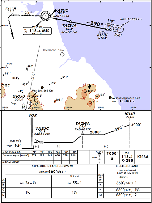
Non precision approach, Misawa Air Base, Japan
In my Hawaii Boeing 707 squadron, we often flew into Misawa Air Base, Japan. The "dive and drive" technique was the mandatory procedure back then so we needed to know when to leave the MDA, which was at 660' MSL. Since the runway was at 94' the math came to:
Looking at the approach plate it appears the end of the runway is at 0.3 DME, so we would use a VDP of 1.9 - 0.3 = 1.6 DME.
Proof
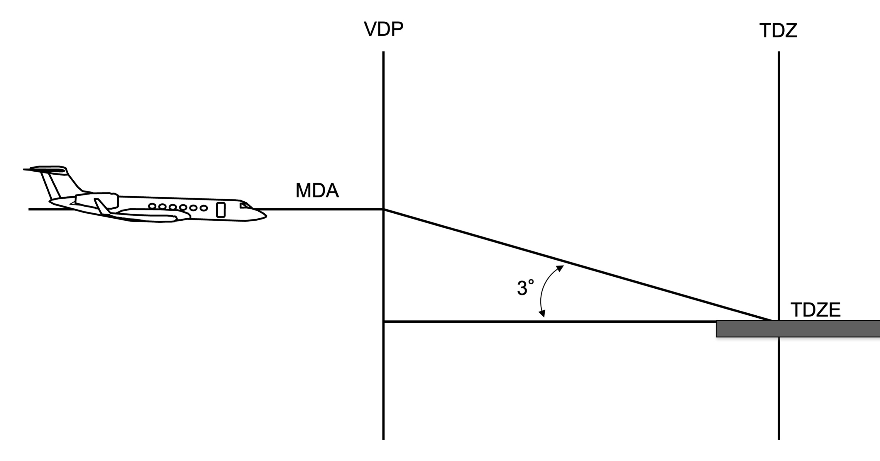
Visual Descent Point (VDP)
The technique is based on the idea that a 3° glide path comes to about 300 feet per nautical mile, and the math follows easily:
Let's say, for example, your MDA is at 1300' and the touchdown zone elevation is 100'. The VDP would be found (1300 - 100) / 300 = 4.0 nm from the touchdown zone. If the airport has a VOR located at the approach end of the runway, the touchdown zone is at (750' / 6076') = 0.1 DME on the other side. Your VDP, then, would be at 3.9 DME on the approach side.
Of course there is an error here, because:
That is only off by 6%, good enough.
11
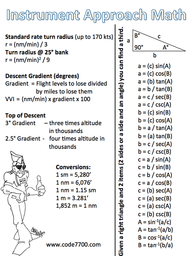
Instrument approach math (a cheat sheet)
You don't need an engineering degree to diagram an approach as shown in these examples. If you can plug and chug with a scientific calculator, all you need are some formulas. Here are some handy ones. (Click on the figure to download a PDF version.