A common question from passengers when looking at all the flight instruments in our cockpits is, “how do you take in so much information at once?” A common answer is, “We are only looking at one thing at a time; we just need to know what to look at when it is relevant.” That answer is true enough, but doesn’t answer the question: how?
— James Albright

Updated:
2024-01-15
The answer used to be a staple of instrument flight and was taught to Air Force pilots before their first flights in primary jet trainers. From the 1976 version of Air Force Manual 51-37, Instrument Flying, issued to me in pilot training:
Aircraft performance is achieved by controlling the aircraft attitude and power (angle of attack and thrust or drag relationship). Aircraft attitude is the relationship of the longitudinal and lateral axis to the earth's horizon. An aircraft is flown in instrument flight by controlling the attitude and power as necessary to produce the desired performance. This is known as the "Control and Performance Concept'' of altitude instrument flying and can be applied to any basic instrument maneuver.
Source: AFM 51-37, ¶2-1
Understanding this deeply was vital in the days before automated cockpits, there was no other way to fly an airplane precisely enough to keep the needles centered for a landing at minimums. These days we think of having to hand-fly an approach to minimums for a check airman as doing it the “old fashioned way,” but the amount a good information in our displays makes the exercise easier than it used to be. This is too bad, because having the control performance technique in your arsenal makes it easier to program the automation and detect when the electrons are not behaving. To really understand the technique, you must first identify the components.
7 — Example: maintaining level flight, making turns
8 — Example: instrument approach
An instrument panel that goes on and on. (From the movie "Airplane")

1
Control instruments
We know we control the aircraft using the stick (or yoke) and rudder as well as the throttles. But we shouldn’t blindly move these controls, we should manipulate them to a desired result as seen on our control instruments.
Moving the stick (or yoke) . . . results in a change in the attitude indicator
Moving power controls (throttle) results in a change seen in the RPM or other engine gauges
With either case, we cannot “set and forget” because each exists in a dynamic environment. You cannot move the stick for a desired pitch, for example, and expect the pitch to stay where you leave it. Your stick and rudder movements are intended to produce a pitch and bank angle but the environment will attempt to change those. You need to target the pitch and bank on the attitude indicator – the control instrument – and check the performance indicator for the desired effect. The same holds true for power controls. You move the throttles to produce the desired RPM or EPR, check and recheck to ensure the desired metric stays where you set it. On many engines, changes to the aircraft’s speed and altitude can impact the RPM or EPR.
2
Performance Instruments
Performance instruments are those that you do not directly set, but are a byproduct of what you’ve done with the control instruments. The aircraft attitude, for example, results in airspeed, altitude, turn rate, heading, and vertical velocity.
3
The procedure
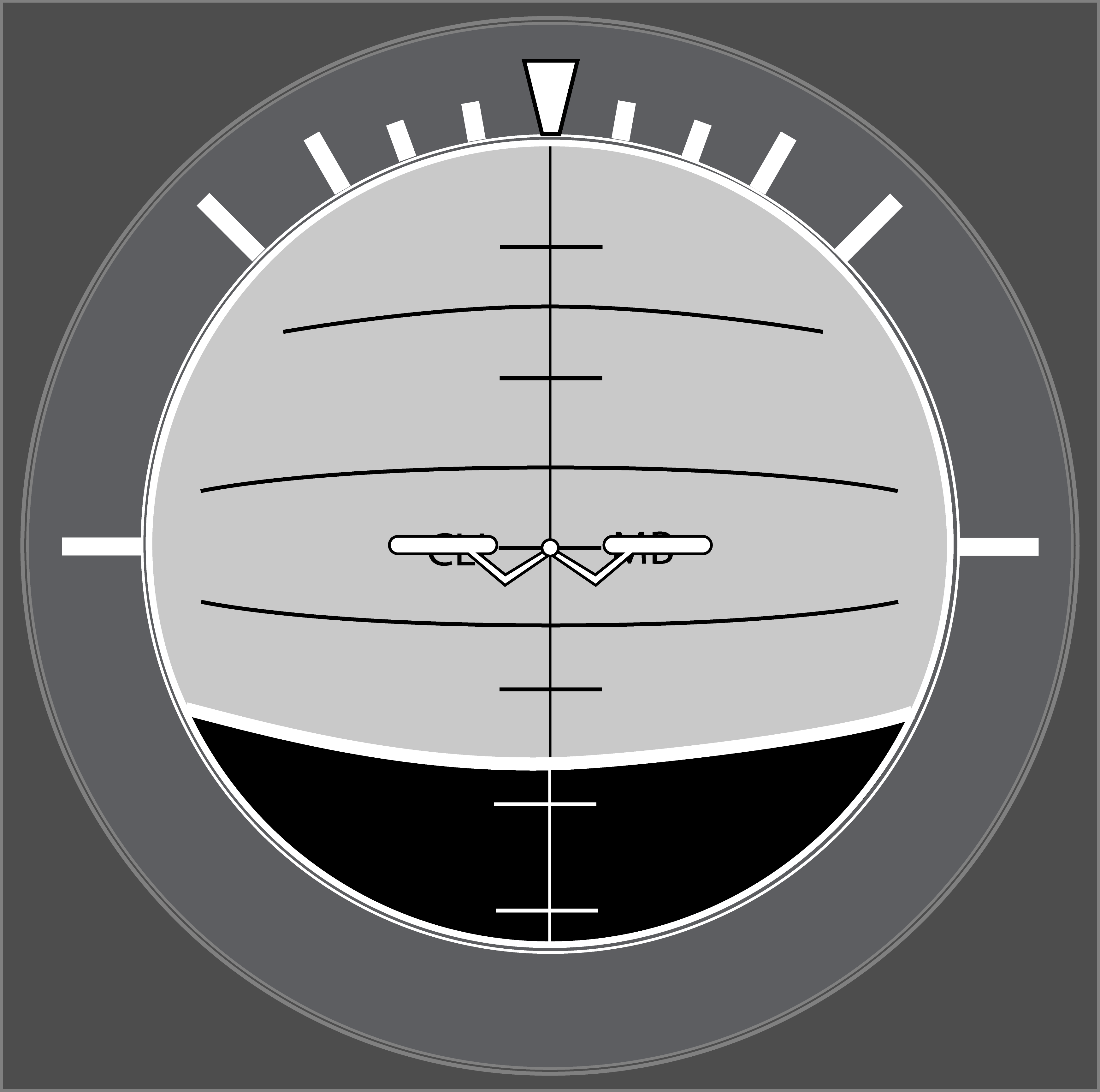
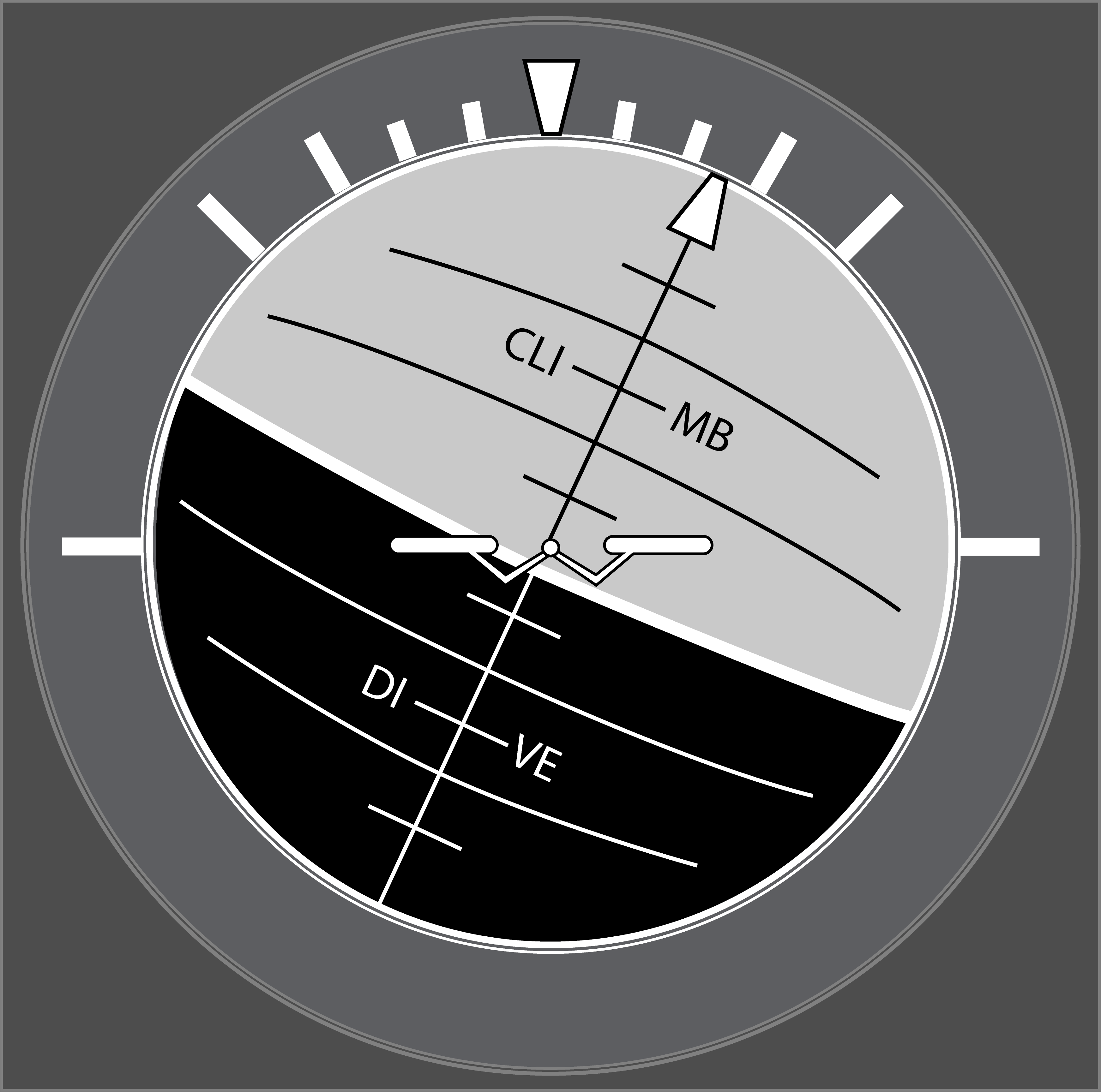
Attitude control
You control the aircraft’s attitude by looking at the aircraft symbol on the attitude indicator while using the stick and rudder in an attempt to keep its relationship to the moving globe behind it constant. Pitch changes are made in degrees nose up and nose down. Attitude indicators may be graduated with a pitch ladder, showing the number of degrees from the horizon. Attitude indicators without a pitch ladder can be manipulated by the thickness of the aircraft symbol center dot or wings, typically 2 degrees. Bank changes are made in relation to bank scale marks, typically at 10, 20, 30, 45, and 60 degrees.
Power control
You control the aircraft’s power by adjusting the throttles to achieve a desired RPM, but also realizing that the aircraft speed and altitude can impact the result. Increasing the aircraft’s speed, for example, can cause some engines to also accelerate. An increase in altitude, for a second example, and cause some engines to decelerate.
Note: purists will argue that some aircraft produce power and others produce thrust, those with propellers rated in power and those without rated in thrust. For our purposes, we’ll use “power” to mean both. Not all engines are controlled using Revolutions Per Minute (RPM) and will rely on other metrics, such as Engine Pressure Ratio (EPR). We will use the RPM gauge to typify and engine’s power/thrust control.
Trim technique
Trimming the flight controls to relieve all control pressures will make it easier to hold a given attitude and devote more attention to navigation and other cockpit duties. An aircraft is trimmed by holding the stick and rudder positions to achieve a desired attitude, and then moving trim controls to relieve all control pressures. It is usually desirable to trim the rudder to produce coordinated flight on the turn and slip indicator (ball centered), and then neutralize aileron pressures to eliminate uncommanded rolls. Differential power can impact both rudder and aileron pressures, so balanced power should be maintained if possible. Changes in attitude, power, and configuration will usually require the trim to be adjusted.
Patience is needed to avoid chasing trim settings. If you find yourself applying trim in one direction and then immediately in the opposite direction, you may be better off freezing all control movements for a second or two so you can reassess trim needs.
4
Instrument limitations
It is important to understand the limitations of each of your flight instruments to understand how frequently they must be scanned as well as to know when the information presented may be suspect.
- Older mechanical attitude indicators may need to be “zeroed” when the aircraft is on the ground or in level flight and can slowly drift away from this zeroed condition. Some attitude indicators can tumble when an attitude exceeds their limitations. Even some modern attitude indicators can be reliant on GPS signals and can become confused when the GPS signal degrades. No matter which type of attitude indicator you have, you need to crosscheck the attitude indicator against relevant performance indicators.
- Most airspeed indicators simply report the pressure of air inside a pitot tube via tubes with no electronics involved. The pressure from the pitot tube is compared to the static pressure outside the aircraft, also via tubes. The result is indicated airspeed that is uncorrected for installation errors and can be subject to contamination outside the skin of the aircraft as well as within those tubes. Of note is the contrary indications when the static source is blocked, and the pitot tube isn’t.
- Altimeters are subject to the same static source errors as airspeed indicators as well as errors resulting from an incorrect barometric setting.
- Conventional vertical velocity indicators are subject to static source errors and a delay in reporting vertical velocity, thought to be as much as 9 seconds. Newer instruments can be computerized to reduce or eliminate the delay.
- Engine speed is often measured in Revolutions Per Minute and mechanical RPM gauges are normally reliable but can “stick” when one of the mechanical parts between the engines and cockpit fail. Even when fully operational, the number produced may not be what the pilot expects. With jet engines, it is impractical to present RPM in actual numbers, such as 23,000 RPM. These engines are usually reported in a percentage of a maximum, but these percentages cannot be thought of as a ratio of available thrust. For example, 50% RPM is probably not 50% of available thrust. The change in thrust settings is rarely proportional. You do not get the same increase in thrust going from 60% to 70% as you do from 80% to 90%. (Generally speaking, the change in relative thrust is higher at higher RPMs.)
- Some engines report thrust as Engine Pressure Ratio, or EPR. In older turbo jets, EPR is derived by measuring the pressure at the inlet and outlet of the engine and dividing the former into the latter. The only jet I’ve ever flown with this arrangement was the Pratt & Whitney J57-P-59W which had a top rating of 2.83 EPR, meaning the outlet pressure was 2.83 times the inlet. Newer, more powerful engines tend to have lower EPRs because the pressures are measured inside the engine and rarely from the outlet. The only thing the pilot can surmise is that a higher EPR means more thrust, but cannot equate these numbers as actual thrust.
In some aircraft, crosschecking one pitot-static instrument against another is useless since they might both use the same source. A blocked static port can mislead not only the altimeter, but the airspeed indicator as well. (See: Aeroperu 603 Case Study.) There is no substitute for understanding the limitations of the instruments in your aircraft and developing an error detection method, a way to crosscheck everything, and if all that fails, to have a backup plan of action.
- Detecting an error: If the attitude indicator is showing you with no bank angle but your heading is changing and the turn and slip indicator confirms the turn, the attitude indicator is suspect. Likewise, if the pitch appears to indicate level flight but the altimeter and airspeed indicators are changing, something is wrong.
- Crosscheck: If you have three attitude indicator, look for agreement of two good to rule out one bad. If you have two attitude indicators that agree, suspect the other instruments but don’t rule out that you might have two bad attitude indicators. With just one attitude indicator, you need to continue investigating.
- Plan B: There are very good portable ADS-B receivers that provide attitude indicators. While these have significant limitations, they can provide the “tie breaker” you need to decide what is working and what isn’t.
- Plan C: A portable GPS can also give you what you need to make sense of cockpit chaos.
5
Crosscheck technique
Cessna T-37B cockpit
The heart of the control performance technique is the ability to detect changes in performance so as to make correct and timely changes to controls. This crosschecking requires you to divide your attention between the control and performance instruments. Typically, we spend about 90% of our attention on the attitude indicator while quickly darting our eyes to the RPM indicator and the various performance indicators. Where you allocate most of your attention after the attitude indicator depends on the location of the instruments, the limitations of those instruments, and what you are doing at the time.
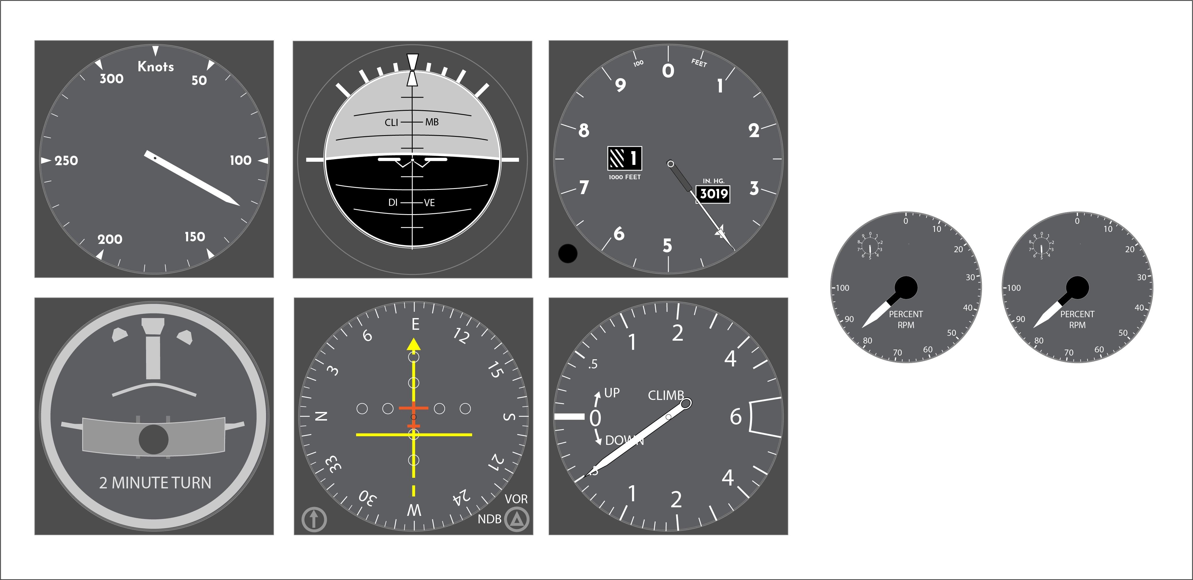
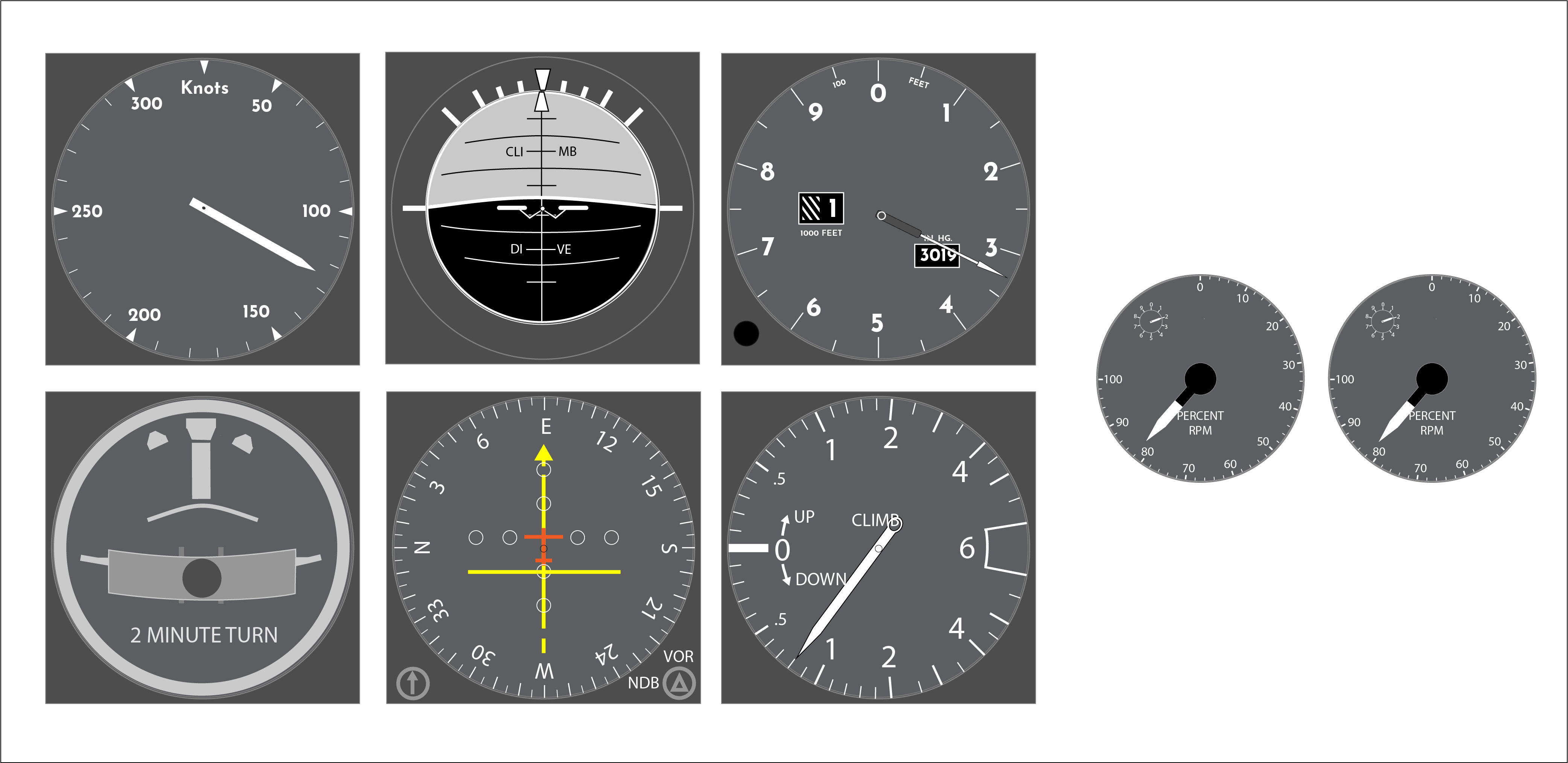
Early instrument cockpits tended to scatter instruments in an almost random order and pilots had to retrain their eyes when moving from airplane to airplane. The distance between instruments could require larger eye movements and pilots had to verify they were looking at the correct instrument before interpreting what they saw. Most modern aircraft have adopted what some call the “six pack” arrangement with the attitude indicator top center, airspeed to the left, altitude to the right, and the bottom row with a turn and slip indicator, heading indicator, and vertical velocity indicator. Because you know precisely where to look and the distance of your eye movement are reduced, location of flight instruments is not as big a factor as it used to be.

Cross check technique
In general, the procedure:
- Use the flight controls to set an attitude and throttles to set engine speed based on experience or known settings for the conditions.
- Maintain attitude and engine speed constant.
- Observe performance instruments (airspeed, altitude, vertical velocity, rate of turn, heading), detect any deviations from the desired values.
- Adjust flight controls and throttles to new values.
- Repeat process, step 2.
What makes the control-performance technique effective is the use of specific values in the control instruments whenever making an adjustment. To illustrate this, we’ll look at a few specific situations.
6
Example: en route climb
During a climb to cruise altitude, we are typically required to set engine speed according to a precomputed setting, removing it as a variable in the problem. Our task then becomes to control airspeed with pitch.
Let’s say that after we’ve cleaned up the aircraft and accelerated to our climb speed of 250 knots, we raise the pitch to capture the speed. From experience, we know that about 15° nose up usually works, so we pull back on the stick to achieve that attitude and trim to neutralize the pressures. We also make sure to keep the wings level unless a turn is needed. Now let’s say the aircraft captures our 250 knots but now slows to 240 knots. A good response would be to push the stick forward and retrim to hold 13° nose up pitch. Now the aircraft accelerates slowly and settles at 253 knots. We can surmise that 15° gives us 240 knots and that 13° gives us 253 knots. It may be prudent to now target 14-½° and evaluate the results anew. As the climb continues, we should be aware that engine speed may need reduction to keep within specified limitations and that pitch will need to be reduced as a result of this and atmospheric conditions.
7
Example: maintaining level flight, making turns
The iterative approach to setting a pitch to maintain level flight is similar to the process used in a climb, though the pitch setting is normally lower. Experience tells us what the pitch setting should be, usually lower at higher altitudes.
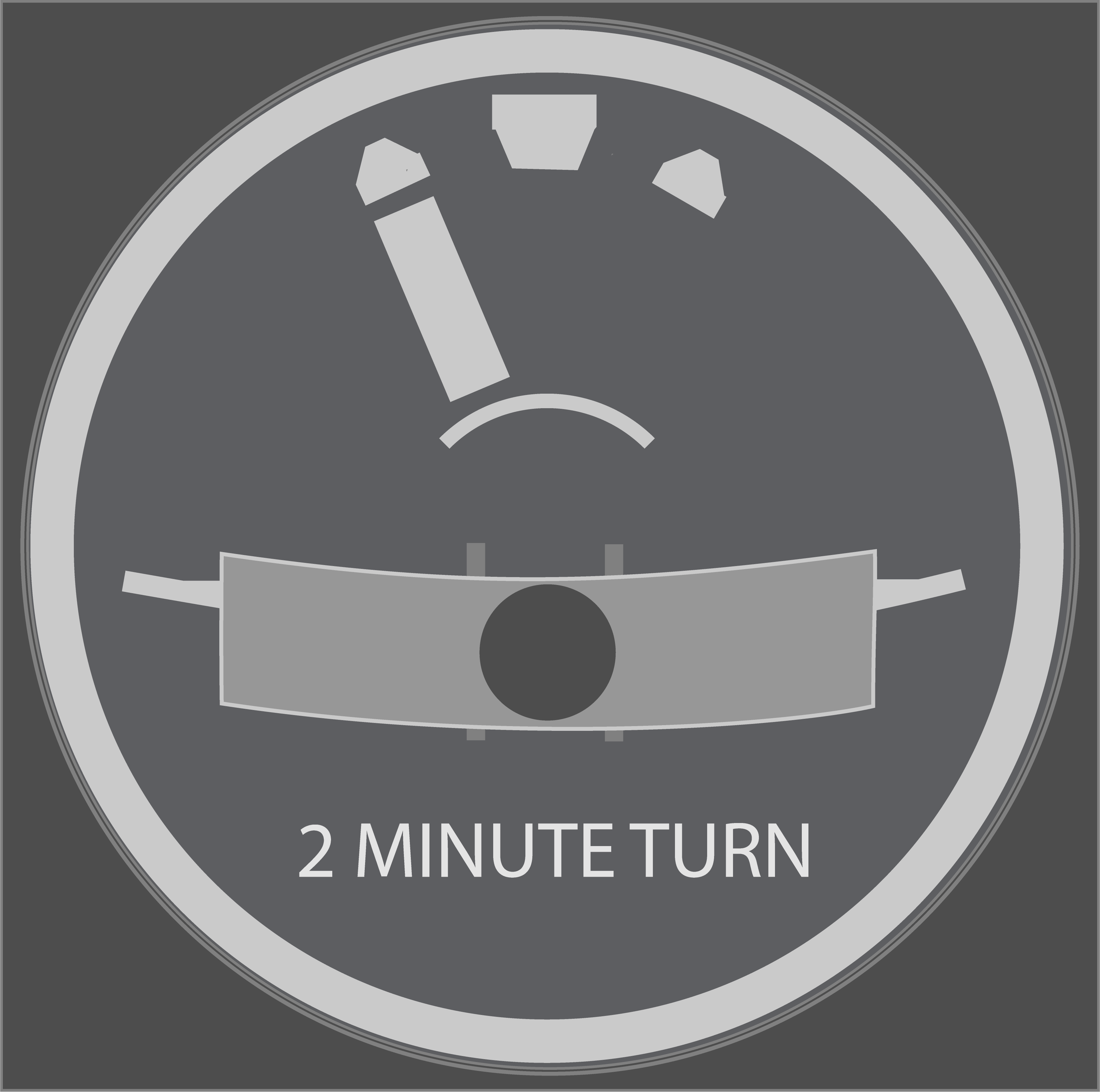
Turns are normally made a standard rate of 2 minutes to make a 360° turn, or at 25° of bank, whichever is less. A standard rate of turn comes to 360 / (2 x 60) = 3° per second. Because this rate of turn will exceed 25° of bank at speed in excess of about 130 knots, most instrument pilots will target 25° of bank rather than a specific rate of turn. The control-performance technique is to move the stick and rudder to achieve the desired pitch and bank, trim off the control pressures, and then monitor rate of turn, altitude, and airspeed. A level flight turn will normally require more engine speed to maintain airspeed.
8
Example: instrument approach
Now let’s say we are flying an ILS approach with the wings level, pitch 2° nose down, and both engines at 85% RPM. Looking at our performance instruments, we are at 125 knots (120 knots desired), on course, one dot above glideslope, and descending at 500 feet per minute (fpm). In short, we are 5 knots hot and a dot high. We know that reducing our pitch will help regain the glideslope but will cause us to accelerate and we are already too fast. Our initial attempt will be to reduce our pitch to 4° nose down and reduce both engines to 82% RPM.
Lowering our pitch increased our vertical speed to 800 fpm; reducing both engines to 82% RPM allowed us to do that without an increase in airspeed. Now we continue to monitor and notice that we are descending nicely to the glideslope but our airspeed hasn’t changed. We know that we can pull more power to fix this, but we also know that once we reach the glideslope we will have to raise the pitch and that will necessitate yet another power change.
Just before the glideslope needle centers, we know we will have to raise the pitch. But how much? Since 2° nose down kept us above glideslope at 500 fpm, we know it will have to be lower than that. Since 4° nose down gave us more than what we needed at 800 fpm, we know it will have to be higher than that. We try 3° nose down and that gives us just what we need at around 600 fpm. We should anticipate the higher pitch will result in a loss of airspeed, so we will need to push the throttles forward. By how much? Once again, we think back to the previous RPMs: 85% RPM on a 500 fpm descent resulted in 5 knots hot, the RPM needs to be lower, 82% RPM on a 800 fpm descent also resulted in 5 knots hot, and 82% RPM on a 600 fpm resulted in losing speed. We can guess that something higher than 82% and lower than 85% will give us what we need.
This iterative process of starting with a number, checking the results, and then adjusting is repeated over and over to narrow the results. It is made easier with experience because your initial “guess” is informed with that experience. I first learned the control-performance technique in 1979 while in Air Force pilot training and it was a required procedure to fly precisely in an unautomated cockpit. What about in a modern computerized airplane?
9
The control performance technique in modern aircraft
Most of the aircraft that I’ve flown in the last twenty-plus years handle the navigation chore from takeoff to landing and most of those also handle the throttles as soon as you push them up before takeoff and remain engaged until after landing. The computers, when working correctly, apply to control and performance technique so quickly that they appear to operate with magical powers. What is left for the pilot to do? Many of us have become spectators in the cockpit.
The problem with becoming an inactive participant on the flight deck is that you are unlikely to detect when there is a problem, caused by you or the airplane. Perhaps two examples will help illustrate the issue, one mundane and the other catastrophic.
Years ago, I gave two check rides to a crew flying two legs in a Bombardier Global Express that had the highest tech cockpit that company had ever produced. The crew allowed the aircraft to make the Top of Descent decision for both legs, waiting for the “TOD” prompt before requesting descent. For the first leg, the prompt came far too early, and we ended up droning at a lower, less fuel-efficient altitude for about ten minutes. For the second leg, descending into the New York City area, the TOD prompt was timely, but the aircraft’s automation was far too leisurely in lowering its pitch. I knew this wouldn’t work out well and politely suggested they decrease their pitch at least three degrees. The pilots were unmoved, saying, “The airplane does that for us.” As if on cue, Air Traffic Control gave them a vector away from the city because they were hadn’t descended quickly enough. During the critique both pilots said the aircraft was buggy and there was nothing to be done about it. I told them they had made a few procedural errors in programming their Flight Management Systems, but I also provided a few techniques on how to anticipate the correct pitch for these situations. The crew was stunned. “Why hasn’t anyone ever taught us this before?”
The next year, my view of the pilots flying for the major airlines was shattered when the crew of Air France Flight 447 plunged their Airbus A330 into the Atlantic, killing all 240 crew and passengers. A simple pitot-static issue caused the autopilot to disengage when the aircraft was at 36,000 feet. In a panic, the pilot flying instinctively pulled back on the stick until the aircraft stalled. In the next moments, none of the pilots recognized that flying at that altitude with the pitch raised beyond 10° nose up could not be sustained. See Case Study: Air France 447.
Known power and pitch settings can be a life saver in any aircraft. What power and pitch setting assures a positive rate of climb without losing speed when low to the ground? What about at the aircraft’s cruise altitude? The answer for many aircraft in the airport traffic area is 10 to 15° nose up at takeoff/go around thrust and between 2° and 3° nose up at climb thrust when at cruise altitude. You should spend some time in the simulator and find the answers for your aircraft, your answers could be very different. The exercise can save you, your passengers, and your aircraft.
The Control Performance Technique was indispensable in the days of cockpits without automation. It continues to be a valuable tool for any pilot’s flight bag.
10
An aside: my earliest surviving note
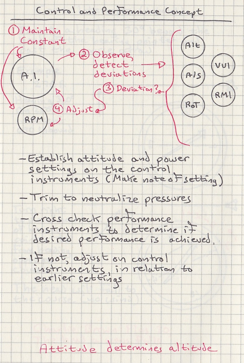
My oldest surviving note
References
(Source material)
Air Force Manual 51-37, Instrument Flying, Department of the Air Force, Washington, 1 December 1976.