The concept of a Required Obstacle Clearance (ROC) is the foundation of instrument flying, it simply means any procedure — departure, en route, approach, missed approach — has to guarantee you a minimum altitude above all obstacles within a certain airspace.
— James Albright

1
TERPS
201. TERPS. Concept of Primary Required Obstacle Clearance (ROC). The title of this order, United States Standard for Terminal Instrument Procedures (TERPS), contains a key word in defining the order's content. The word is "STANDARD;" something set up and established by authority as a rule for the measure of quantity, weight, extent, value, or quality.
a. The TERPS document specifies the minimum measure of obstacle clearance that is considered by the FAA (the Federal authority) to supply a satisfactory level of vertical protection. The validity of the protection is dependent, in part, on assumed aircraft performance. In the case of TERPS, it is assumed that aircraft will perform within certification requirements.
b. The following is an excerpt from the foreword of this order: "These criteria are predicated on normal aircraft operations for considering obstacle clearance requirements." Normal aircraft operation means all aircraft systems are functioning normally, all required navigational aids (NAVAID's) are performing within flight inspection parameters, and the pilot is conducting instrument operations utilizing instrument procedures based on the TERPS standard to provide ROC. While the application of TERPS criteria indirectly addresses issues of flyability and efficient use of NAVAID's, the major safety contribution is the provision of obstacle clearance standards. This facet of TERPS allows aeronautical navigation in instrument meteorological conditions (IMC) without fear of collision with unseen obstacles. ROC is provided through application of level and sloping OCS.
Source: TERPS, ¶201.

TERPS, ¶202a, figure 1-1.
202. Level OCS. The level OCS concept is applicable to “level flight” segments. These segments are level flight operations intended for en route, initial, intermediate segments, and non-precision final approaches. A single ROC value is applied over the length of the segment. These values were determined through testing and observation of aircraft and pilot performance in various flight conditions. Typical ROC values are: for en route procedure segments, 1,000 feet (2,000 over designated mountainous terrain); and for initial segments, 1,000 feet, 500 feet in intermediate segments, and 350/300/250 feet in final segments.
a. This method of applying ROC results in a horizontal band of airspace that cannot be penetrated by obstacles. Since obstacles always extend upward from the ground, the bottom surface of the ROC band is mathematically placed on top of the highest obstacle within the segment. The depth (ROC value) of the band is added to the obstacle height to determine the minimum altitude authorized for the segment. The bottom surface of the ROC band is referred to as the level OCS. Therefore, level flight segments are evaluated by the level OCS application standard.
Source: TERPS, ¶202.

Slope ratio
203. Sloping Obstacle Clearance Surfaces (OCS). The method of applying ROC, in segments dedicated to descending on a glide path or climbing in a departure or missed approach segment, requires a different obstacle clearance concept than the level OCS because the ROC value must vary throughout the segment. The value of ROC near the runway is relatively small, and the value at the opposite end of the segment is sufficient to satisfy one of the level surface standards above. It follows then, that a sloping OCS is a more appropriate method of ROC application.
NOTE: Slope ratios are normally expressed in terms of rise over run in engineering and professional technical jargon. However, TERPS has traditionally expressed slope ratios in terms of run over rise; e.g., 34:1, 40:1.
a. Descending on a Precision Glide Path The obstacle evaluation method for descent on a glide path is the application of a descending OCS below the glide path The vertical distance between the glide path and the OCS is ROC; i.e., ROC = (glide path height) - (OCS height). The ROC decreases with distance from the final approach fix as the OCS and glide path converge on the approach surface baseline (ASBL) height. The OCS slope and glide path angle values are interdependent: OCS Slope = 102 ÷ glide path angle; or glide path angle = 102 ÷ OCS slope. This relationship is the standard that determines the ROC value since ROC = (glide path height) - (OCS height).

TERPS, ¶203a, figure 1-2.
(1) If the OCS is penetrated, the OCS slope may be adjusted upward, thereby increasing the glide path angle. The glide path angle would increase because it is dependent on the required slope.
(2) Descent on a glide path generated by systems that do not meet the system precision requirements of ICAO PANS-OPs, Annex 10, such as barometric vertical navigation (Baro-VNAV), provide ROC through application of a descending sloping surface based on standards using differing formulas, but the concept is the same.
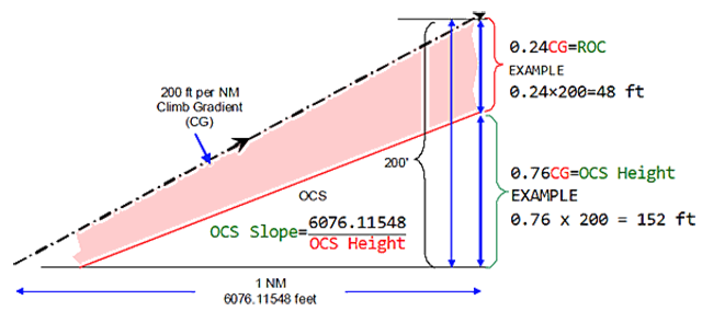
b. Climbing on departure or missed approach. The concept of providing obstacle clearance in the climb segment, in instrument procedures, is based on the aircraft maintaining a minimum climb gradient. The climb gradient must be sufficient to increase obstacle clearance along the flight path so that the minimum ROC for the subsequent segment is achieved prior to leaving the climb segment (see figure 1-3). For TERPS purposes, the MINIMUM climb gradient that will provide adequate ROC in the climb segment is 200 ft/NM.
(1) The obstacle evaluation method for a climb segment is the application of a rising OCS below the minimum climbing flight path Whether the climb is for departure or missed approach is immaterial. The vertical distance between the climbing flight path and the OCS is ROC. ROC for a climbing segment is defined as ROC = 0.24 CG . This concept is often called the 24% rule. Altitude gained is dependent on climb gradient (CG) expressed in feet per NM. The minimum ROC supplied by the 200 ft/NM CG is 48 ft/NM (0.24 × 200 = 48). Since 48 of the 200 feet gained in 1 NM is ROC, the OCS height at that point must be 152 feet (200 - 48 = 152) , or 76% of the CG (152 ÷ 200 = 0.76). The slope of a surface that rises 152 over 1 NM is 40 (6076.11548 ÷ 152 = 39.97 = 40).
Source: TERPS, ¶203.
TERPS, ¶202b, figure 1-3.
(2) Where an obstruction penetrates the OCS, a nonstandard climb gradient (greater than 200 ft/NM) is required to provide adequate ROC. Since the climb gradient will be greater than 200 ft/NM, ROC will be greater than 48 ft/NM (0.24 x CG > 200 = ROC > 48). The nonstandard ROC expressed in ft/NM can be calculated using the formula: (0.24 h) = (0.76 d) where "h" is the height of the obstacle above the altitude from which the climb is initiated, and "d" is the distance in NM from the initiation of climb to the obstacle. Normally, instead of calculating the nonstandard ROC value, the required climb gradient is calculated directly using the formula: h ÷ (0.76d).
c. In the case of an instrument departure, the OCS is applied during the climb until at least the minimum en route value of ROC is attained. The OCS begins at the departure end of runway, at the elevation of the runway end. It is assumed aircraft will cross the departure end-of-runway at a height of at least 35 ft. However, for TERPS purposes, aircraft are assumed to lift off at the runway end (unless the procedures state otherwise). The ROC value is zero at the runway end, and increases along the departure route until the appropriate ROC value is attained to allow en route flight to commence.
d. In the case of a missed approach procedure, the climbing flight path starts at the height of MDA or DA minus height loss. The OCS starts approximately at the MAP/DA point at an altitude of MDA/DA minus the final segment ROC and adjustments. Therefore, the final segment ROC is assured at the beginning of the OCS, and increases as the missed approach route progresses. The OCS is applied until at least the minimum initial or en route value of ROC is attained, as appropriate.
e. Extraordinary circumstances, such as a mechanical or electrical malfunction, may prevent an aircraft from achieving the 200 ft/NM minimum climb gradient assumed by TERPS. In these cases, adequate obstacle clearance may not be provided by published instrument procedures. Operational procedures contained outside TERPS guidelines are required to cope with these abnormal scenarios.
Source:
TERPS does not apply in extraordinary circumstances. If you declare an emergency, your commitment to TERPS is over. But it is up to you to find other operational procedures. During takeoff, for example, you can fall back on AC 120-91 Airport Obstacle Analysis as covered by Departure Obstacle Avoidance.
TERPS, ¶260a, figure 15-1.
260. CIRCLING APPROACH AREA. Where circling is authorized, evaluate the circling approach area for each CAT published on the procedure. The Circling Minimum Descent Altitude (CMDA) is based on the results of the circling area evaluation and the evaluation of the final segment delivering the aircraft to the circling area.
a. Obstacle Evaluation Area (OEA). The area for each CAT is based on true airspeed (VKTAS). The minimum altitude used for true airspeed conversion is 1,000 ft above airport elevation. Use the following formula for converting indicated airspeed (VKIAS) to true airspeed (VKTAS) is:
Calculate the Circling Approach Radius (CAR) based on true airspeed, bank angle, and straight segment length using the following formula (radian calculations):
Where:
VKTAS = true airspeed
bankangle = bank angle (from table 4)
S = straight segment (from table 4)
*Minimum CAR = 1.30 NM
| CAT V | KIAS | Bankangle | Straight Segment Length (S) |
| A | 90 | 25 | 0.4 |
| B | 120 | 25 | 0.4 |
| C | 140 | 20 | 0.5 |
| D | 165 | 20 | 0.6 |
| E | 200 | 22 | 0.7 |
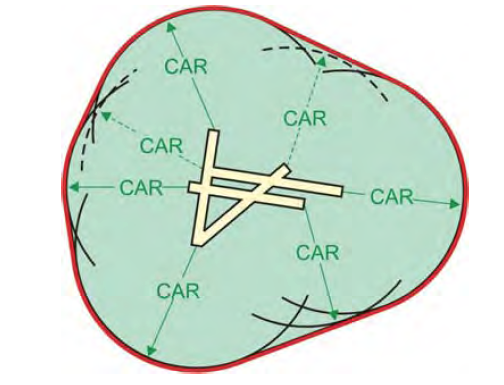
The OEA is constructed by drawing arcs equal to the CAR for each CAT from the RWT coordinates (or displaced threshold coordinates when applicable) of each runway. Not applicable to permanently closed or other runways not authorized for circling. However, when only one end of the runway is not authorized for circling, the OEA is based on the CAR from both sets of RWT coordinates. Join the outermost arcs with tangential lines. The resulting enclosed area is the circling OEA [no secondary area].
b. Obstacle Clearance. Provide 300 ft Required Obstacle Clearance plus adjustments over the highest obstacle in the Obstacle Evaluation Area.
Source: TERPS, ¶260.
2
ICAO

ICAO Doc 8168 Vol 1, figure I-2-1-2.
1.3.1 Where track guidance is provided in the design of a procedure, each segment comprises a specified volume of airspace, the vertical cross-section of which is an area located symmetrically about the centre line of each segment. The vertical cross-section of each segment is divided into primary and secondary areas. Full obstacle clearances are applied over the primary areas reducing to zero at the outer edges of the secondary areas
1.3.2 On straight segments, the width of the primary area at any given point is equal to one-half of the total width. The width of each secondary area is equal to one-quarter of the total width.
1.3.3 Where no track guidance is provided during a turn specified by the procedure, the total width of the area is considered primary area.
1.3.4 The minimum obstacle clearance (MOC) is provided for the whole width of the primary area. In the secondary area, MOC is provided at the inner edges reducing to zero at the outer edges
Source: ICAO Doc 8168 Vol 1 §2, Chapter 1
1.4.1 The minimum obstacle clearance equals zero at the departure end of the runway (DER). From that point, it increases by 0.8 per cent of the horizontal distance in the direction of flight assuming a maximum turn of 15°.
1.4.2 In the turn initiation area and turn area, a minimum obstacle clearance of 90 m (295 ft) is provided.
1.4.3 Where precipitous and mountainous terrain exist, consideration is given by the procedures designer to increasing the minimum obstacle clearance.
3.3.1 Unless otherwise specified, departure procedures assume a 3.3 per cent (helicopters, 5 per cent) PDG and a straight climb on the extended runway centre line until reaching 120 m (394 ft) (helicopters, 90 m (295 ft)) above the aerodrome elevation.
3.3.2 The basic procedure ensures:
a) the aircraft climbs on the extended runway centre line to 120 m (394 ft) before turns can be specified; and
b) at least 90 m (295 ft) of obstacle clearance is provided before turns greater than 15° are specified.
Source: ICAO Doc 8168 Vol 1 §3, Departure Procedures

ICAO Doc 8168 Vol 1, figure I-4-1-2.

ICAO Doc 8168 Vol 1, figure I-4-1-3.

ICAO Doc 8168 Vol 1, figure I-4-1-4
References
(Source material)
ICAO Doc 8168 - Aircraft Operations - Vol I - Flight Procedures, Procedures for Air Navigation Services, International Civil Aviation Organization, 2006
United States Standard for Terminal Instrument Procedures (TERPS), Federal Aviation Administration 8260.3B CHG 25, 03/09/2012