I was in Aspen about fifteen years ago, sitting in the FBO with at least ten other crews all doing the same thing: looking at the overcast. The Obstacle Departure Procedure for the Aspen-Pitkin County/Sardy Field Airport (KASE) simply says, "use SARDD DEPARTURE." That departure procedure requires the weather be at least 400-1 and mandates a climb of at least 460 feet per nautical mile all the way up to 14,000 feet.
— James Albright
— With an opinion in the See and avoid section by Chris Parker

Updated:
2016-03-01
"If we can't see the obstacles," I explained to our lead passenger, "we have to out-climb them. Our Gulfstream is too heavy to do that so we have to wait until the weather improves to VFR." Just then all heads in the FBO turned to the runway to see another Gulfstream take off and disappear into the clouds. Was that crew operating foolishly or was I being overly cautious? I made it my highest priority to figure this out: what is the best strategy when dealing with departure obstacles?
There are many strategies when it comes to dealing with this problem, some better than others. I'll group them all into three major categories, look at the pros and cons, and then recommend a strategy.

1
The issues

Aspen Airport at Night, Courtesy Tom Cuccio
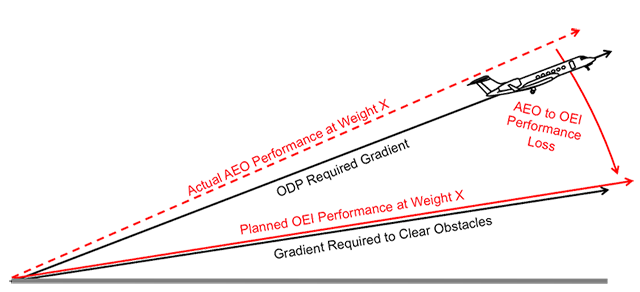
Issue: All-Engines-Operating (AEO) versus One-Engine-Inoperative (OEI)
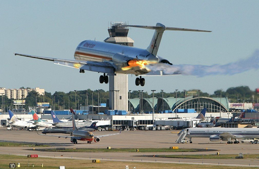
MD-82, St. Louis, Associated Press (Photoshopped?)
Departure procedures assume AEO
- Both U.S. and ICAO departure procedures are built on the assumption that everything is working, including the engines. The U.S. departure procedure rules are covered in the United States Standard for Terminal Instrument Procedures (TERPS), Federal Aviation Administration 8260.3B, Volume 1, ¶201.
- The ICAO departure procedures are covered in the ICAO Doc 8168 - Aircraft Operations - Vol II - Construction of Visual and Instrument Flight Procedures, Procedures for Air Navigation Services.
These criteria are predicated on normal aircraft operations for considering obstacle clearance requirements.
The design of procedures in accordance with this section assumes normal operations and that all engines are operating.
Airworthiness standards assume OEI
- Both U.S. and ICAO aircraft certification rules for transport category aircraft assume failure of the critical engine. The U.S. rules are covered by 14 CFR 25, §25.111.
- The ICAO Airworthiness rules are covered by ICAO Annex 8
The airplane must be accelerated on the ground to VEF, at which point the critical engine must be made inoperative and remain inoperative for the rest of the takeoff.
The take-off path shall comprise the ground or water run, initial climb and climb-out, assuming the critical engine to fail suddenly during the take-off.
Some pilots dismiss 14 CFR 25 and ICAO Annex 8 as not really applicable to flight operations since they have more to do with aircraft certification than pilot procedures. True or not, these rules cause aircraft manufacturers to focus only on OEI data so most aircraft certified under these rules present only OEI takeoff performance data. This greatly impacts turbine aircraft performance planning, especially when dealing with takeoff obstacles. This is why the classic, "old school" method of dealing with departure obstacles is to use engine-out data. (In most aircraft that is all you have.)
Issue: Regulations versus Regulations
U.S. Federal Aviation Regulations (Vertical & Lateral)
If you are operating under U.S. commercial regulations you must use an obstacle clearance or avoidance procedure that ensures you clear the obstacles by specific margins.
For an airplane certificated after September 30, 1958 (SR422A, 422B), that allows a net takeoff flight path that clears all obstacles either by a height of at least 35 feet vertically, or by at least 200 feet horizontally within the airport boundaries and by at least 300 feet horizontally after passing the boundaries.
Source: 14 CFR 135, §135.379
These aren’t very large clearances — basically 35 feet vertically and 300 feet horizontally — but you do have to clear the obstacles.
What about non-commercial operators? You still need to avoid hitting anything because of the so-called "reckless" rule.
No person may operate an aircraft in a careless or reckless manner so as to endanger the life or property of another.
Source: 14 CFR 91, §91.13
Some operators call this the "scrape paint" rule. You have to "just" clear the obstacle vertically and horizontally. For the sake of the discussion that follows, we'll assume our 14 CFR 91 operators have the good sense to strive for the same obstacle clearance standards of their commercial peers.
It became obvious these margins were far too thin with the dawn of large jet airliners. At first the rules were tailored for the Boeing 707 but eventually those rules were tossed out in favor of the so-called "net takeoff flight path" flight path instituted by 14 CFR 25. While this regulation never mentions a "gross" flight path, it does have the following to say about the net flight path.
The net takeoff flight path data must be determined so that they represent the actual takeoff flight paths reduced at each point by a gradient of climb equal to—
(1) 0.8 percent for two-engine airplanes;
(2) 0.9 percent for three-engine airplanes; and
(3) 1.0 percent for four-engine airplanes.
Source: 14 CFR 25, §25.115
This is misunderstood by many as "test pilot versus real pilot" rules. That is completely wrong. The "gross path" is what the airplane actually does with you at the controls. In fact, you would be better off if you replaced the word "gross" with the word "actual" when it comes to takeoff climb performance. The regulations and your flight manual are based on the actual numbers minus the shown reductions. You can consider this a "safety pad." You and the airplane produce gross (actual) numbers, the books are based on net numbers.
Does that mean you can simply add the net reduction back in and call it good? Or just subtract it from the obstacle departure procedure gradient? Why not just subtract 0.8 percent from the required climb gradient in a two-engine airplane? That gains you (0.008)(6076) = 48 feet every nautical mile! But what about winds? What about an aircraft that might not be as clean as the day it was certified? What about pilot technique? In my opinion, it is foolish to give up this margin.
There are those who argue that you don't really need to follow anything in a departure procedure if you are flying under Part 91. The rules, after all, are for the commercial guys. The shortest regulation in the book tells us otherwise . . .
(a) This part prescribes standard instrument approach procedures to civil airports in the United States and the weather minimums that apply to landings under IFR at those airports.
(b) This part also prescribes obstacle departure procedures (ODPs) for certain civil airports in the United States and the weather minimums that apply to takeoffs under IFR at civil airports in the United States.
Source: 14 CFR 97, §97.1
In the United States, every instrument approach, arrival, and departure procedure is regulatory. If you are flying under instrument flight rules, you have to obey everything on that plate.
U.S. TERPS (Vertical)
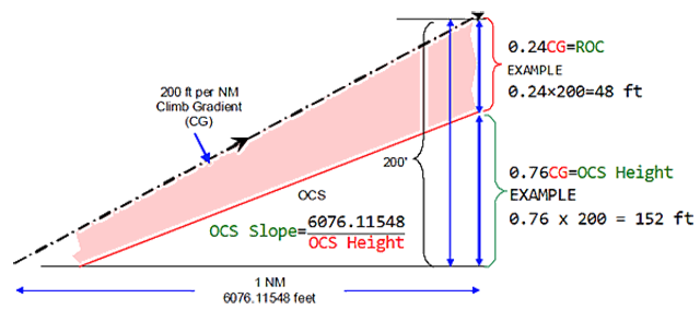
TERPS, ¶202b, figure 1-3.
If you are flying an instrument procedure in the United States, chances are it was designed under the criteria set down by the United States Standard for Terminal Instrument Procedures, also known as "TERPS" or Federal Aviation Administration 8260.3B. TERPS has other names with various branches of the U.S. military and it is also used by various foreign governments without their own airspace design authorities. If you are flying an obstacle departure procedure designed under TERPS, there are a few things you need to know about departure obstacle avoidance.
When flying a TERPS-designed ODP, you are given a minimum Climb Gradient (CG) of 200 feet per nautical mile and a minimum Required Obstacle Clearance (ROC) of 48 feet per nautical mile. These values of CG and ROC remain so long as no obstacles (with an exception to be covered later) penetrate an Obstacle Clearance Surface (OCS) derived as 152 feet per nautical mile. If an obstacle does penetrate the OCS (other than the exception to be covered shortly), the CG and ROC are increased to maintain at least a 24 percent buffer between the flight path and the obstacle. These rules in TERPS are covered in Volume 1, ¶203.
For TERPS purposes, the MINIMUM climb gradient that will provide adequate ROC in the climb segment is 200 ft/NM.
The vertical distance between the climbing flight path and the OCS is ROC. ROC for a climbing segment is defined as ROC = 0.24 CG . This concept is often called the 24 percent rule.
Where an obstruction penetrates the OCS, a nonstandard climb gradient (greater than 200 ft/NM) is required to provide adequate ROC.
The nonstandard ROC expressed in ft/NM can be calculated using the formula: (0.24 h) ÷ (0.76d) where "h" is the height of the obstacle above the altitude from which the climb is initiated, and "d" is the distance in NM from the initiation of climb to the obstacle.
Source: TERPS, Volume 1, ¶203
Note that the ROC is defined as being 24 percent of the CG. The minimum ROC comes to 48 feet at 1 nautical mile because (0.24)(200) = 48 feet. If the CG increases, the ROC increases too. So, for example, if you have a 300 feet per nautical mile climb gradient, your ROC at 1 nautical mile will be (0.24)(300) = 72 feet.
U.S. TERPS (Lateral)
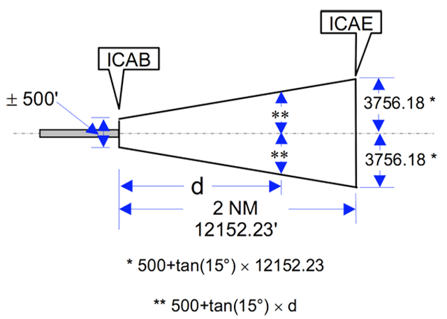
TERPS, Vol 4, figure 1-5.
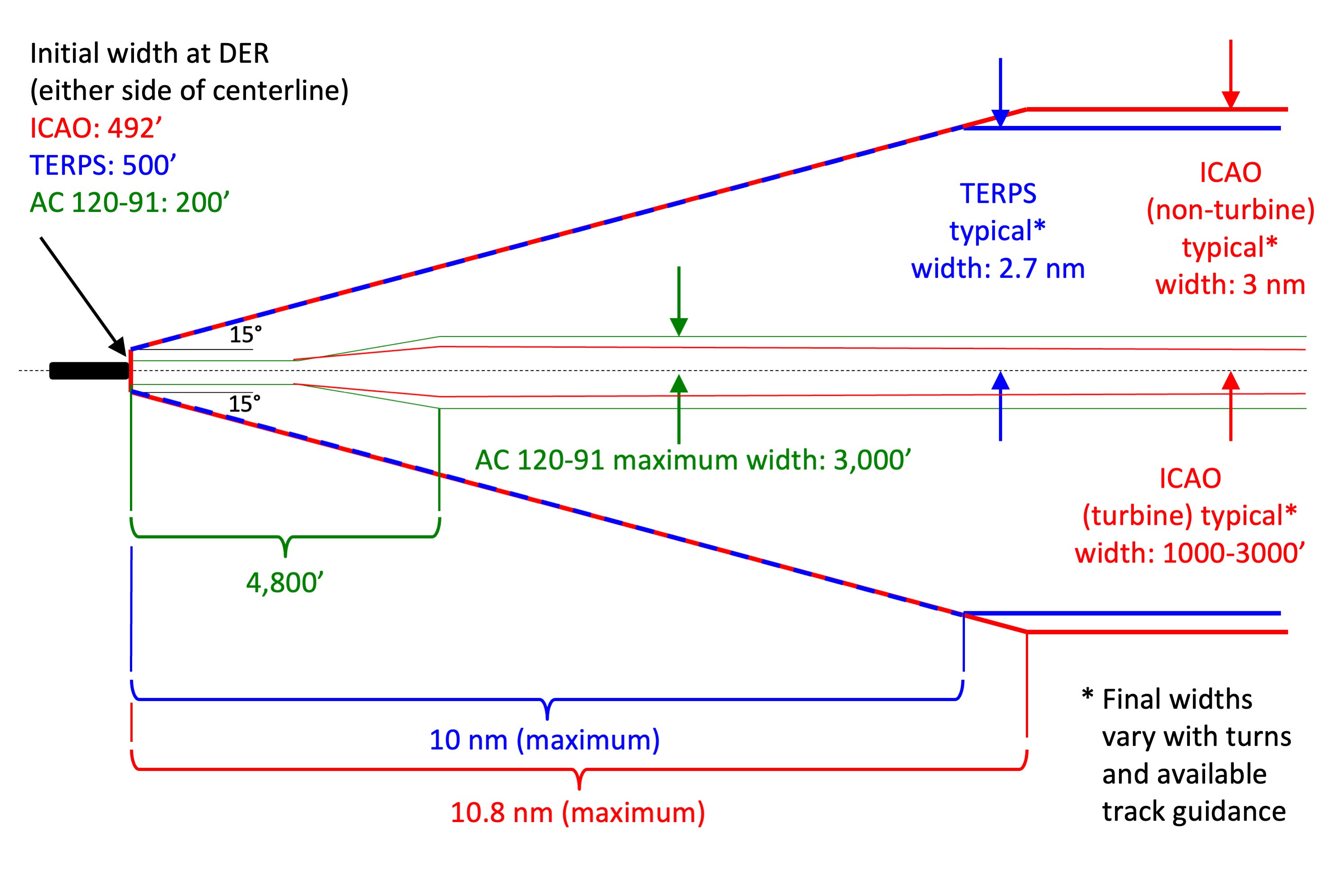
While most pilot texts covering departure obstacles pay heed to the need to maintain an increasing flight path vertically over obstacles, many fail to consider which obstacles. If your takeoff flight path takes you right over an obstacle that is obvious enough. But what if that obstacle is a mile to the left once you've already traveled five miles? Do you need to clear that obstacle? It depends on the rules that apply. Under TERPS, the Initial Climb Area (ICA) starts out at 500 feet left and right of runway centerline at the Departure End of Runway (DER). It normally ends 2 nautical miles later but could be extended for 10 nautical miles. You will have to consider all obstacles up to 500 feet of centerline at first, extending to a width that can vary from 3,756 feet to just under 3 nautical miles. All of this is covered by TERPS, Volume 4, ¶1.6.
The Initial Climb Area Baseline (ICAB) is a line extending perpendicular to the runway centerline 500 at DER. The splay of 15° and length of the ICA determine its width. The ICA length is normally 2 NM. The ICA may be extended beyond 2 NM to maximum length of 10 NM.
Source: TERPS, Volume 4, ¶1.6
This is the simplest and narrowest of the possible departure procedures; the lateral margins increase with turns and can vary with available course guidance. Having to out-climb an obstacle that is over two miles away laterally would seem nonsensical. U.S. rules recognized this with the adoption of Advisory Circular 120-91.
U.S. AC 120-91 (Lateral)
It has been rather obvious to the airlines that U.S. TERPS departure procedure designs are overly restrictive, but the narrow margins afforded by commercial regulations are too risky. Over a series of many years of collaborative research the FAA released Advisory Circular 120-91, Airport Obstacle Analysis, which specifies a more realistic standard when it comes to lateral margins.
The Area Analysis Method defines an obstacle accountability area (OAA) within which all obstacles must be cleared vertically. The OAA is centered on the intended flight track and is acceptable for use without accounting for factors that may affect the actual flight track relative to the intended track, such as wind and available course guidance.
During straight-out departures or when the intended track or airplane heading is within 15 degrees of the extended runway centerline heading, the minimum width of the OAA is 200 feet on each side of the intended track within the airport boundaries, and 300 feet on each side of the intended track outside the airport boundaries. During departures involving turns of the intended track or when the airplane heading is more than 15 degrees from the extended runway centerline heading, the maximum width of the OAA is 3,000 feet on each side of the intended track.
Source: AC 120-91, ¶ 10, 11, 12
If you operate using the guidance of AC 120-91, you can narrow your lateral margins from nearly 3 miles down to only 3,000 feet of each wing tip. In other words, you no longer have to restrict your takeoff weight to out-climb that obstacle sitting over a half-mile to one side.
ICAO Regulations (Vertical)
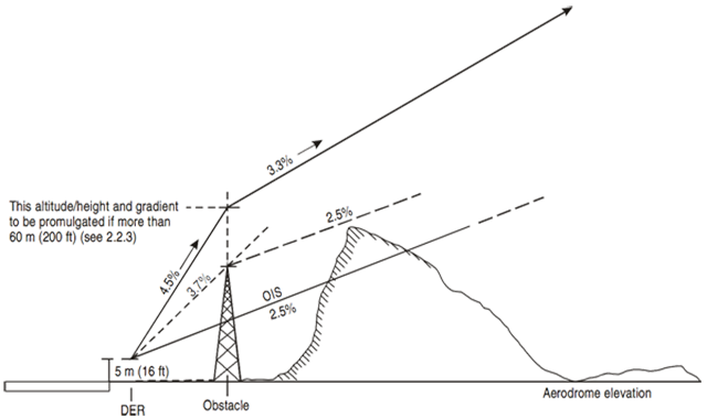
ICAO Doc 8168 Vol II, figure I-3-2-2.
The ICAO also provides for a net takeoff flight path, similar to 14 CFR 25, that requires the AFM performance be reduced by set margins. If a factor is applied during certification, such as is the case for transport category aircraft certified in the United States, that factor is used. If no factor is given, the ICAO provides a net factor for 2 and 4 engine aircraft that are more conservative. If your aircraft was certified under 14 CFR 25, you will use the FAA rules.
The term “net take-off flight path”, as relating to the aeroplane, has its meaning defined in the airworthiness requirements under which the aeroplane was certificated. If this definition is found inadequate, then a definition specified by the State of the Operator should be used.
The net take-off flight path is the one-engine-inoperative flight path which starts at a height of 10.7 m (35 ft) at the end of the take-off distance required and extends to a height of at least 450 m (1,500 ft) calculated in accordance with the conditions of 2.9, the expected gradient of climb being diminished at each point by a gradient equal to: 0.5 per cent, for aeroplanes with two engines, 0.8 per cent, for aeroplanes with four engines.
Source: ICAO Annex 6, Part I, ATT C
As with the 14 CFR 25 definition, aircraft manufacturers are compelled to publish AFM performance numbers with the net flight path performance numbers. What this means to the pilot is that the airplane will actually climb better than predicted by their manuals. Some pilots talk of increasing the AFM performance by this so-called "net takeoff flight path" factor. I recommend you do not do this. The added margin becomes a safety factor to account for changes in wind and temperature, as well as variation in pilot technique. Besides, you have other vertical margins to consider.
If you are flying an obstacle departure procedure designed under ICAO rules, you are given a 0.8 percent margin between the Procedure Design Gradient (PDG) and the obstacle. This margin is the Minimum Obstacle Clearance (MOC), akin to the TERPS Required Obstacle Clearance (ROC) but smaller.
The standard procedure design gradient (PDG) is 3.3 per cent. The PDG begins at a point 5 m (16 ft) above the departure end of the runway (DER).
The standard PDG provides an additional clearance of 0.8 per cent of the distance flown from the DER, above an obstacle identification surface (OIS). The OIS has a gradient of 2.5 per cent.
Where an obstacle penetrates the OIS, a steeper PDG may be promulgated to provide obstacle clearance of 0.8 per cent of the distance flown from the DER.
The minimum obstacle clearance (MOC) in the primary area is 0.8 per cent of the distance flown from the DER. The MOC is zero at the DER.
Source: ICAO Doc 8168 Vol II, ¶2
ICAO uses a 3.3 percent line drawn from 5 meters above the departure end of the runway to construct what they call the Procedure Design Gradient (PDG). This is identical to the U.S. TERPS 200 feet per nautical mile climb gradient, since 100 (200 / 6076) = 3.3 percent, except for the matter of how far above the runway this gradient begins. The Obstacle Identification Surface (OIS) is used to identify if adjustments are needed to the standard PDG. The OIS has a gradient of 2.5 percent, which is identical to the U.S. TERPS 152 feet per nautical mile Obstacle Clearance Surface (OCS), since 100 (152 / 6076) = 2.5 percent.
The ICAO adjusts the PDG upwards to maintain a 0.8 percent Minimum Obstacle Clearance (MOC) above all obstacles. Unlike the rule in U.S. TERPS, the ICAO will allow the climb gradient to change back to 3.3 percent once the obstacle has been passed.
ICAO Regulations (Lateral)
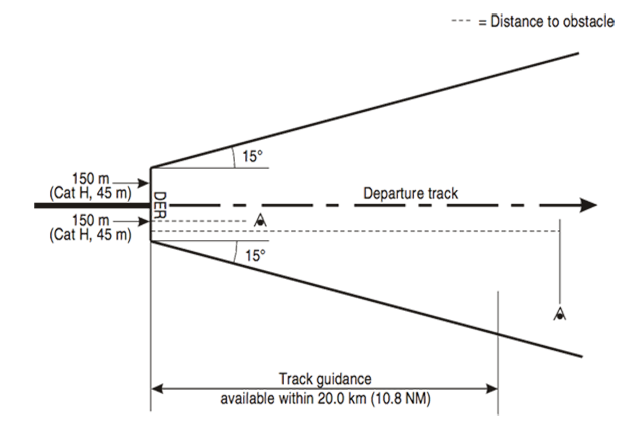
ICAO Doc 8168 Vol II, figure I-3-3-1.
ICAO obstacle departure procedures are built with lateral margins that are even more generous than those found in U.S. TERPS.
The area begins at the DER and has an initial width of 300 m (Cat H, 90 m).
The departure procedure ends at the point where the PDG reaches the minimum altitude/height authorized for the next phase of flight.
Source: ICAO Doc 8168 Vol II, ¶3.2.4.1
This is the simplest and narrowest of the possible departure procedures; the lateral margins increase with turns. Note that it begins at 150 meters (492 feet) either side of centerline and gets as wide as 150 + (20,000) tan(15) = 5,659 meters (just over 3 nautical miles).
The ICAO narrows the area an operator must consider when flying a turbine-powered aircraft over 5,700 kg maximum certificated takeoff mass.
No aeroplane should commence a take-off at a mass in excess of that shown in the flight manual to correspond with a net take-off flight path which clears all obstacles either by at least a height of 10.7 m (35 ft) vertically or at least 90 m (300 ft) plus 0.125D laterally, where D is the horizontal distance the aeroplane has traveled from the end of take-off distance available.
Where the intended track does not include any change of heading greater than 15°, for operations conducted in VMC by day, or for operations conducted with navigation aids such that the pilot can maintain the aeroplane on the intended track with the same precision as for operations specified in 5.1.1 a), obstacles at a distance greater than 300 m (1,000 ft) on either side of the intended track need not be cleared.
Where the intended track does not include any change of heading greater than 15° for operations conducted in IMC, or in VMC by night, except as provided in 5.1.1 b); and where the intended track includes changes of heading greater than 15° for operations conducted in VMC by day, obstacles at a distance greater than 600 m (2,000 ft) on either side of the intended track need not be cleared.
Where the intended track includes changes of heading greater than 15° for operations conducted in IMC, or in VMC by night, obstacles at a distance greater than 900 m (3,000 ft) on either side of the intended track need not be cleared.
Source: ICAO Annex 6, Part I, ATT C
For turbine powered aircraft that weigh more than 5,700 kg (12,566 pounds) the margins are narrowed considerably, depending on turns and course guidance. The maximum lateral width is 3,000 feet but can be as little as 1,000 feet.
Issue: ICAO versus TERPS
Vertical
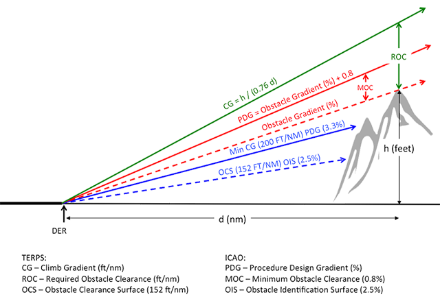
Climb gradient requirement comparison
There are a few differences in the way the ICAO and the U.S. FAA (through TERPS) address obstacles that will impact what you can do to avoid them. You cannot address the vertical component of obstacle avoidance without also considering the lateral component. If the obstacle is right below you, of course, you must out-climb it. What if it is 100 feet to your right? How about a mile? For now let's table the lateral discussion and simply look at the vertical.
The minimum climb gradient. Both ICAO and TERPS specify a minimum climb gradient for all departure procedures. The ICAO calls this the Minimum Procedure Design Gradient (PDG) and says it can never be less than 3.3 percent. In the U.S., TERPS calls this the Minimum Climb Gradient (CG) and says it can never be less than 200 feet per nautical mile. These values are about the same, since 200/6076 = 0.033 and that is another way of writing 3.3 percent.
The obstacle clearance / identification surface. Both ICAO and TERPS specify a surface below the aircraft's path that identifies a zone where obstacles cannot penetrate without having to change the climb gradient. There is an exception to this for Low, Close-In Obstacles, but more on that later. The ICAO calls this the Obstacle Identification Surface (OIS) and defines it as a surface starting at the Departure End of Runway (DER) inclined upward by 2.5 percent. In the U.S., TERPS calls this the Obstacle Clearance Surface (OCS) and defines it as a surface that starts at the DER inclined upward by 152 feet per nautical mile. The values are about the same, since 152/6076 = 0.025 and that is another way of writing 2.5 percent.
Minimum / Required Obstacle Clearance. If you take the minimum climb gradient and subtract the obstacle surface you get the safety margin between the two. If you simply look at the minimum climb gradient where no obstacles penetrate the identification / clearance surface, both ICAO and TERPS provide for about the same margin. Under ICAO you have 3.3 - 2.5 = 0.8 percent. Under TERPS you have 200 - 152 = 48 feet per nautical mile, and that comes to (48 / 6076) = 0.0079, or about 0.8 percent. But as the climb gradient increases, the TERPS value increases. Here TERPS jumps from using feet per nautical mile to percentages, but the TERPS percentage is different.
- Under ICAO, a Minimum Obstacle Clearance (MOC) of 0.8 percent of the distance from the DER is specified. Mathematically, MOC = (0.008) (d).
- Under TERPS a Required Obstacle Clearance (ROC) of 24 percent of the Climb Gradient is specified. Mathematically, ROC = (0.24) CG.
Adjusting climb gradient for obstacles. If an obstacle, other than a Low, Close-In Obstacle (more on that later) penetrates the OIS / OCS, the procedure's climb gradient must be raised to preserve the MOC / ROC.
- Under ICAO, the 0.8 percent MOC is added to the gradient created by the obstacle. If, for example, a line from the DER to the obstacle is 5 percent, the Procedure Design Gradient is raised to 5.8 percent.
- Under TERPS, the Climb Gradient is adjusted to the following formula:
You can compute the resulting ROC = (0.24) (CG), which is why they call this the "24 percent rule." Yes, the ROC is larger than the MOC, but the numbers 24 and 0.8 exaggerate the difference because they are percentages of different things.
Vertical Example
Let's say we have an obstacle that is 1500 feet above and 5 nm (30,380 feet) away from the DER.
Under ICAO, the obstacle has a gradient of (1500 / 30380) = 0.0494, or 4.94 percent. The MOC is always 0.8 percent so our PDG is 4.94 + 0.8 = 5.74 percent. Our height above the obstacle would be (0.0574)(30380) - 1500 = 244 feet.
Under TERPS, the climb gradient is h / (0.76 d), or 1500 / (0.76 x 5) = 395 feet per nautical mile. (That's 6.5 percent, much higher than the ICAO PDG.) So our ROC = (0.24) (395) = 95 feet per nautical mile. At 5 nm, our height above the obstacle will be (5)(95) = 475 feet. You can also derive this by figuring your altitude (5)(395) = 1,975, subtracting the obstacle height (1,500 feet) to arrive at the same answer, 475 feet.
Is 244 feet (ICAO) or 475 feet (TERPS) a comfortable margin? Keep in mind that if your multi-engine turbine aircraft was certified under 14 CFR 25, you will also have the net takeoff flight path margin. A twin-engine aircraft, for example, will be (0.008) (5) (6076) = 243 feet higher than the AFM states, unless there is a tailwind or temperature inversion. Only you can decide this, but you will need to give it some thought. Chipping away at this vertical margin is a fundamental step in the techniques to follow.
Lateral
Obstacle area lateral comparison
Obstacle departure procedures are designed with very wide lateral tolerances under both ICAO and TERPS, which means those minimum climb gradients could be unnecessarily high because they are considering obstacles miles away from course centerline. Of course this was necessary back when an aircraft climbing into a cloud deck was lucky to be within a mile of course. But these days? If you have an airplane with an instantaneous readout of "position uncertainty" you very seldom see your airplane more than 0.05 nautical miles off course. Three hundred feet! While departure procedures continue to be built off these wide lateral areas, we as pilots are allowed to narrow our gaze if we have a plan to do that.
Original ODP Designs. TERPS procedure construction can be very complicated; the lateral margins vary with distance from the departure end of the runway, relationship to the airport boundary, any turns, and available track guidance. The lateral margin starts at 200 feet either side of runway centerline and quickly expands by thousands of feet, to as much as 3 miles. ICAO procedure construction mimics TERPS in many ways and becomes almost as wide. Unless the procedure says otherwise, the climb gradient on these procedures could be based on obstacles that you will have no chance of seeing.
Tighter Lateral Margins. ICAO Annex 6 narrows the lateral margin for large (more than 5,700 kg, about 12,500 lbs.) turbine aircraft. The margin can be as tight as 1,000 feet but will be no more than 3,000 feet (about a half nautical mile), depending on course guidance, turns, and distance from the runway. U.S. Advisory Circular 120-91 provides a method of applying a obstacle clearance area that is much more narrow than TERPS and is almost as narrow as the tightest ICAO margin. If an aircraft can maintain course within 3,000 feet (about a half nautical mile), the result can be a significant increase in payload.
Lateral Example
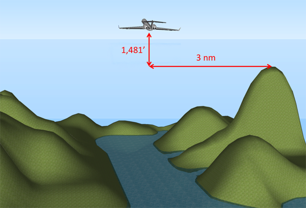
3-D Terrain Model, TERPS, Aft View
Let's say you are departing in a two-engine aircraft from an airport that leads into a valley with what looks to be a challenging obstacle departure procedure. The SID says you need to climb at 400 ft/nm to an altitude that is 4,000 ft above the departure end of the runway. Looking at the chart you see a number of mountains and it appears the greatest problem will be around 10 nm after takeoff about 3 nm to the right. The departure takes you right down the middle of the valley, so can you improve your situation by keeping to the course centerline better than 3 nautical miles? How high above the obstacle will you really be?
- The formula for finding the climb gradient in a TERPS procedure is CG = h / (0.76 x d), where h is the obstacle height in feet and d is the distance from the DER in nautical miles. We can run the formula backwards to find h = CG (0.76) d = 400 (0.76) (10) = 3,040 feet above the DER.
- The procedure required obstacle clearance is ROC = (0.24) CG = (0.24) (400) = 96 ft/nm, which means at 10 nm it will be 960 feet.
- since the aircraft was certified under 14 CFR 25, you also know it will outperform the AFM net takeoff flight path by 0.8 percent, which means at 10 nm it will be (0.008)(10)(6076) = 486 feet higher than the charts say.
- While TERPS assumes the departure begins at DER on the runway, your aircraft manuals are usually predicated on 35 feet. If the aircraft was certified with wet runway takeoff performance, it may be predicated on crossing the DER at 15 feet in wet runway conditions. Let's say the runway is dry and you cross the DER at 35 feet, which means you will be that much higher abeam the obstacle.
- That means you will cross abeam the obstacle 960 + 486 + 35 = 1,481' higher than the obstacle.
Combining the Vertical and Lateral Examples
3-D Terrain Model, AC 120-91, Aft View
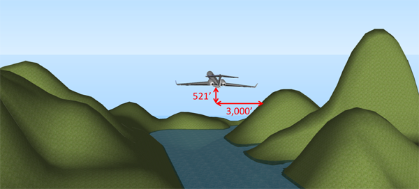
In our example, if you lose an engine at V1 and manage to keep the aircraft on the departure procedure's course centerline, you will be 1,481 feet above (vertically) and 3 nautical miles away (laterally). If you don't lose an engine, you will of course be much higher.
You have several vertical margins at work: the 35 feet required by 14 CFR 135.379 (which you cannot give up), the net takeoff flight path margin (0.8 percent for a two-engine aircraft), and the 24 percent Required Obstacle Clearance afforded by TERPS. Giving up the ROC would still leave you a margin of 35 + (10)(0.008)(6076) = 521 feet above and abeam the obstacle.
We will shortly examine a method that addresses the vertical margins and another that addresses the vertical and lateral margins. But first, there is a more immediate problem with all obstacle departure procedures, regardless of the number of engines operating . . .
Issue: The Low, Close-In Problem, Theory versus Reality
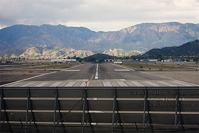
Burbank Runway 33, from Kurt Preisler
There is a catch when it comes to low, close-in obstacles under both ICAO and U.S. TERPS departure procedures. You are expected to avoid them using "see and avoid" or procedural techniques, but you aren't given precise location information. This information is detailed in Volume 4 of TERPS.
Where low, close-in obstacles result in a climb gradient to an altitude 200 feet or less above DER elevation . . . publish a note identifying the obstacle(s) type, location relative to DER, AGL height, and MSL elevation.
Source: TERPS Vol 4, ¶ 1.4.6
The 200 feet or less implies any obstacles below 200 feet above DER within 1 nm of the DER because the standard climb gradient is 200 ft/nm. Higher and farther obstacles require a change to published climb gradients and possibly to takeoff minimums. But those low, close-in obstacles require only a note.
Do not publish a CG to a height of 200 feet or less above the DER elevation. Annotate the location and height of any obstacles that cause such climb gradients.
Source: TERPS Vol 4, ¶ 1.3.1
The same "catch" exists under ICAO.
An increased gradient that is required to a height of 60 m (200 ft) or less, (normally due to low, close-in obstacles) shall not be promulgated. The position and elevation/height of close-in obstacles penetrating the OIS shall be promulgated
Source: ICAO Doc 8168 Vol II, ¶2
Where it all falls apart with this low, close-in obstacle methodology is the "publish a note identifying the obstacle(s)" proviso. To see this in action, consider Runway 33 at Bob Hope Airport (KBUR) at Burbank, California.
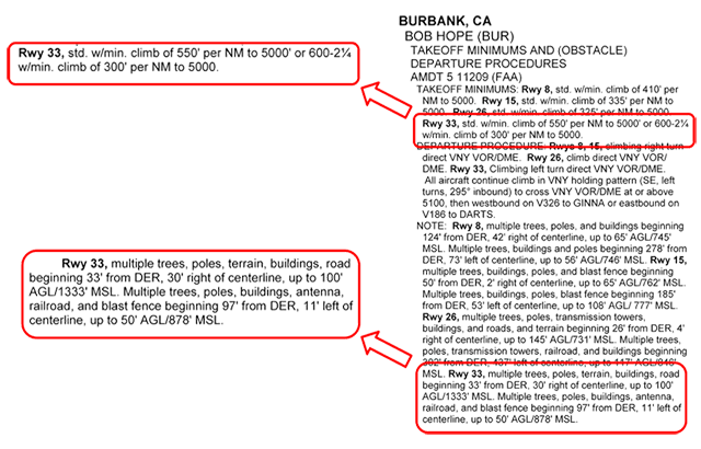
Takeoff Minimums, (Obstacle) Departure Procedures.
At first reading the published notes seem ridiculous. Can there possibly be a 100' obstacle 33' from the DER just 30' right of centerline? I would have noticed! The word "beginning" explains the rationale behind the poorly worded sentence but does little to help the pilot. Where are these obstacles, exactly? They are not drawn precisely (if at all) on the airport diagrams and a sectional is useless at this level of detail. The FAA does offer a digital obstacle file for the United States at http://www.faa.gov/air_traffic/flight_info/aeronav/digital_products/dof/ but these are very large, cumbersome, and would take a good computer to really digest. If you wanted to try, you will see that the file covering KBUR is 790 pages long and includes these two gems:
06-030661 O US CA BURBANK 34 12 56.17N 118 21 50.28W POLE 1,00050 00846 R 2 C U A 2013106
06-001786 O US CA BURBANK 34 12 52.00N 118 21 41.00W POLE 1,00048 00831 L 1 A U C 2014152
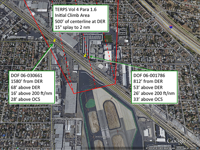
Obstacles, pinpointed.
So if you were able to find these two obstacles out of the thousands given, and if you plotted them, you would see where exactly your low, close-in obstacles are.
Is this a problem? Almost never. Almost. In our example, let's say it is raining, the weather is above standard and you are permitted to leave with the minimum climb gradient of 300 ft/nm to 5,000 feet. That comes to 300 / 6076 = 4.94 percent. If the maximum weight for this climb gradient requires a ground run following an engine failure that equals the runway available, you can expect to cross the DER at 15 feet. A 4.94 percent gradient across a distance of 812 feet results in a climb of (0.0494) (812) = 40 feet. If you cross the DER at 15 feet that means you are at 40 + 15 = 55 feet when you cross the pole marked as DOF 06-001786, which is 53 feet above the DER. You have a clearance of 2 feet!
How to out-climb low, close-in obstacles
If you are departing an airport with ambiguous notes about low, close-in obstacles the only thing you can be sure of is that they are out there. You can examine the area with your own eyes, comb through digital obstacle files, or simply out-climb them. If you cross the DER at 200 feet you know you will be above them all. To do this, you will need to know how much runway you must have left over when you lift off. You can figure this out by multiplying 6076 by 200, and dividing all that by the climb gradient in feet per nautical miles. If, for example, the AFM says you will be climbing at 400 feet per nautical mile, you will need to have (6076)(200) / (400) = 3038 feet of the runway remaining when you lift off.
Of course this is a ridiculous solution to what should be a simple problem. If you are going to be using all of that runway and there is any doubt about the low, close-in obstacles, the airport manager should be able to help with a more specific idea of where these obstacles are. There is, fortunately, an even easier solution. (See below, A High Tech Strategy.)
Now that we've covered most of the issues involved with departure obstacle avoidance, let's look at three possible strategies.
2
Strategies
The Old School Strategy: Use AFM OEI Performance With Published AEO Departure Procedures
Not too many years ago the vast majority of pilots would tell you that the only way to legally and safely depart a mountainous airport was to look at the departure procedure, look at your Airplane Flight Manual (AFM) performance charts, and make everything agree. So let's try the Aspen Obstacle Departure Procedure (ODP) with my favorite example airplane, the Gulfstream G450.
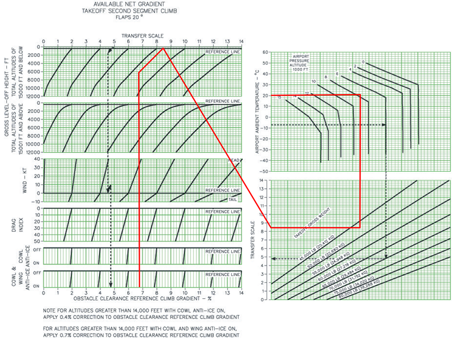
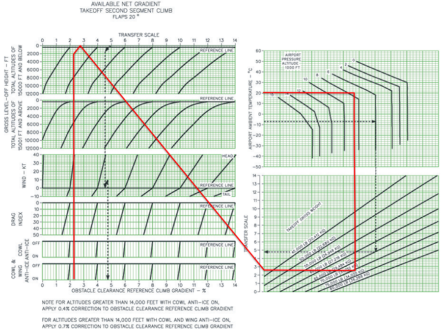
G450 Net Gradient Takeoff Second Segment Chart
Chasing through the charts it looks like an impossible task. We find the appropriate charts in the G450 AFM, §05-06-00, Figure 3. Our first task is to compute the climb gradient. The departure tells us we need 460 feet per nautical mile. We know a nautical mile is 6,076 feet, therefore:
But the Gulfstream manual tells us this is a "gross climb gradient" and that we should subtract 0.8 percent so that it becomes a net takeoff flight path climb gradient. It seems the manual wants us to give up this safety margin when flying an obstacle departure procedure with no further explanation. Since we know there are other safety margins out there, we dutifully enter the chart with a value of:
Chasing up the chart we find we need a "Gross Level-off Height" which the AFM says we can find by subtract the elevation of the Departure End of Runway (DER) from the MSL level off:
We come up with a transfer scale number of 8.4. Entering the next chart at 20°C and 7600' pressure altitude we find our maximum grossweight will be around 48,000 lbs. Since our airplane has a BOW of around 43,000 lbs, we won't have enough gas to make it to Denver with any kind of reserve. Since we are trying to make it back to the east coast, that only leaves us with one option: wait for the weather to improve so we no longer have to comply with the climb gradient.
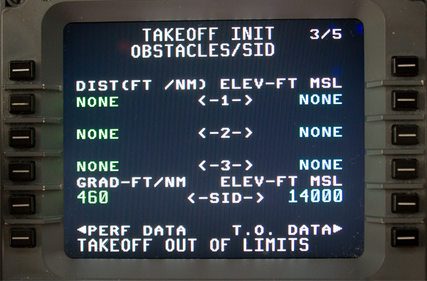
G450 MCDU Takeoff Data Page 1/3
Meanwhile your copilot remembers that the aircraft FMS has a performance computer that can automate those silly spaghetti charts and enters all the appropriate data. With this FMS you enter climb gradient in feet per nautical mile to a stated elevation (MSL) in feet.
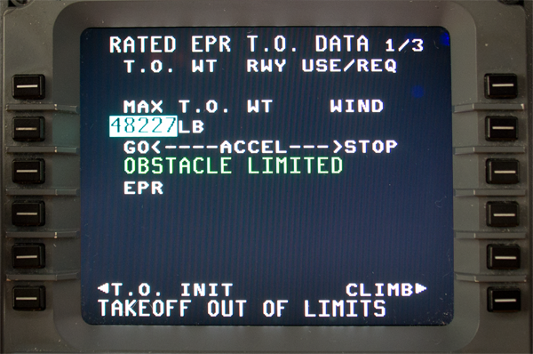
G450 MCDU Takeoff Data Page 1/3,
The answer, unfortunately, comes up very close to those spaghetti charts.
Remember that this number assumes you need to avoid all obstacles within very large vertical and lateral margins. Though the Gulfstream solution immediately gives up the net takeoff flight path 0.8 percent performance margin, you still have the 24 percent Required Obstacle Clearance that isn't really required at all if you lose an engine. There is room for improvement . . .
A Low Tech Strategy: Reduce the Vertical Margins
The Strategy
Meeting the ODP climb gradient with OEI
There is a strategy in use by many operators and provided for by several commercial vendors to simply subtract either the ICAO 0.8 percent MOC or the TERPS 24 percent ROC from the Obstacle Departure Procedure (ODP) climb gradient. Since very few aircraft manufacturers supply All-Engine-Operative (AEO) takeoff climb performance data, we've normally ensured we meet the ODP climb gradient with One-Engine-Inoperative (OEI). We know that if we can make the climb gradient with an engine failed, we'll have no problems with all engines operating.
You can do this, but there are three caveats:
- If you lose an engine, you must clear all obstacles by 35 feet vertically and 200, 300, or up to 3,000 feet laterally depending on your distance from the airport and which rules apply. (If you've reduced your climb gradient by the MOC or the ROC, you should be okay since they are designed with this in mind and the net takeoff flight path margin is still there.)
- If you lose an engine, you should declare an emergency so ATC knows you will not be climbing as expected and that they should "clear the way."
- If you do not lose an engine, you must still make the ODP climb gradient.
Meeting the ODP obstacle clearance gradients with OEI
So let's say you've figure a new, higher gross weight by reducing the climb gradient by 24 percent on a TERPS departure procedure. Instead of a 400 feet per nautical mile gradient, for example, you enter your performance computer with (1 - 0.24) 400 = 304 feet per nautical mile. If you lose an engine, you will clear the obstacles and don't have to worry about the procedure's climb gradient. But if you don't lose the engine, will you still make the required climb gradient? You are in uncharted territory.
Ensuring All-Engine-Operating (AEO) Performance at Higher Weights
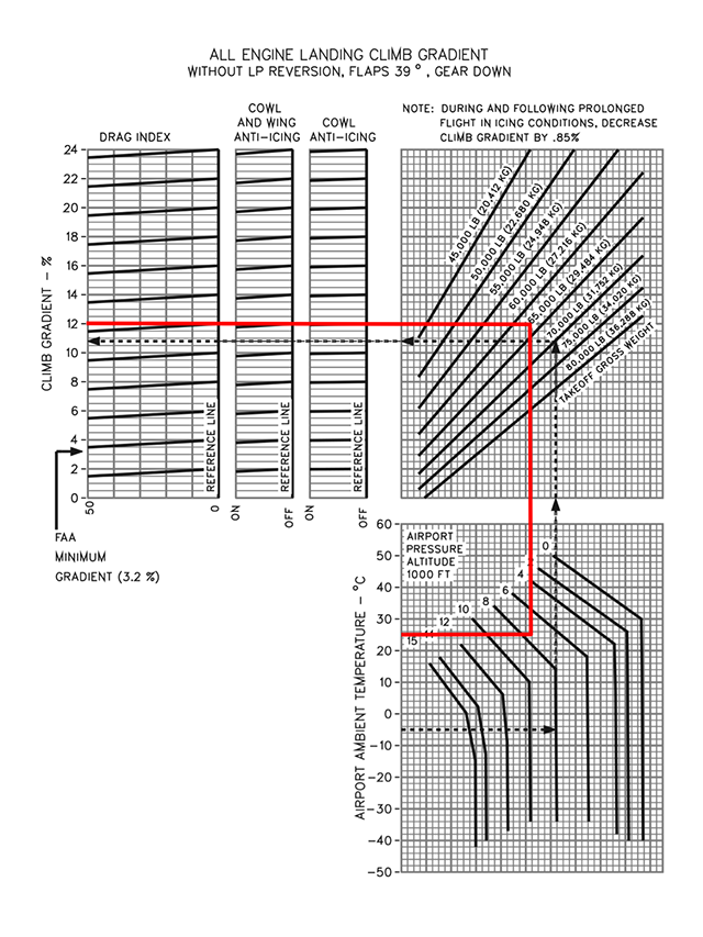
G450 AOM, §13-02-10, figure 2
If your AFM does not include AEO takeoff climb data you might have a problem, but you might find something that gives you something that is a conservative analog. In the G450, for example, we have a chart that produces all engine climb data with the gear down and flaps fully extended to 39°. If the airplane can make the climb gradient in this configuration, it can surely do so with the gear up and a smaller angle of flaps:
Even if you don't have any conservative chart that gives you the necessary reassurance, you might be okay. Let's say, as with the Aspen example, you have a ODP climb gradient of 7.6 percent and elect to reduce that by the TERPS 24 percent ROC, lowering your OEI climb gradient to (1 - 0.24) (7.6) = 5.8 percent. You know you will clear the obstacles because the climb gradient minus the ROC based on that. Now if you don't lose an engine what is your AEO climb gradient? What follows is my personal theory.
- If you are flying a two-engine aircraft you are getting half your climb gradient from each engine. If you lose an engine, your climb gradient decreases by at least 50 percent because you will also have the parasite drag from the wind milling or seized engine.
- It follows, then, that your all-engine climb gradient will be at least double your one-engine climb gradient.
- Since you've reduced your target climb gradient by a maximum of 24 percent and will have double the climb gradient available, you should be okay.
- Since the loss of an engine in a three-engine aircraft results in 33 percent thrust loss and in a four-engine aircraft results in a 25 percent thrust loss, each aircraft should be okay since the maximum gradient reduction is 24 percent.
Should? There might be something I haven't thought of here. I've tested this in the simulator in a GIV, GV, G450, and CL-604. See the G450 results here: Takeoff Climb Performance AEO Versus OEI. I encourage you to do the same. Our results have been very good. If, for example, the OEI climb gradient was 8 percent our AEO gradient was easily 20 percent. To do this, have the simulator operator record the aircraft's flight track and depart on an ODP twice, once with an engine failed at V1 and once with an all-engine aircraft.
Back to the Aspen Example
We can examine the SARDD obstacle departure procedure from Aspen to better understand these margins. Recall that we were unable to depart Runway 33 at Aspen under Instrument Flight Rules because we could not meet the 460 feet per nautical mile climb gradient all the way to 14,000 feet.
Using terrain mapping software, such as Google Earth, you can draw the obstacle departure procedure course line from the Departure End of Runway (DER) all the way to the completion of the procedure. You can also diagram the borders of the obstacle clearance area and discover the most challenging obstacles are about a mile right of course. This is a laborious process and no pilot should be expected to do this. But this examination will help illustrate what exactly is going on when you choose to reduce your vertical margins to make an obstacle departure procedure climb gradient.
- The published climb gradient is 460 feet per nautical mile, which comes to (460 / 6076) = 7.57 percent
- The Departure End of Runway (DER) is 7,680 feet. We will reach 14,000 feet in (14000 - 7680) / 460 = 13.74 nm
- A theoretical controlling obstacle height can be derived from the TERPS formula:
- From this we derive the obstacle gradient that is controlling our procedure's climb gradient, it is:
- Using Google Earth, we can produce a terrain elevation profile for an on course departure (shown below in blue) and for one deviates to the right inside the TERPS obstacle clearance area until it is 1 nautical mile to the right (shown in red). Right of course we see an obstacle at 9,250' MSL, 4.5 nm from the DER. This obstacle will be 9250 - 7680 = 1,570 feet above the DER. We can compute its gradient:
- We can repeat this process for what appears to be the most challenging obstacle if the airplane were to remain precisely on course, a peak of 8,700 feet found 7.2 nm from DER. The peak is 8700 - 7680 = 1,020 feet above DER. The gradient of this obstacle is:
From this we see h = (0.76) (d) (CG) = (0.76) (13.74) (460) = 4804 feet
(Pretty close to the theoretical gradient.)
This is less than the 2.5 percent ICAO OIS and the TERPS 152 ft/nm OCS, since (0.0233)(6076) = 142 ft/nm. If you could remain on course you would only need the minimum 200 ft/nm (TERPS) 3.3 percent (ICAO) climb gradient!
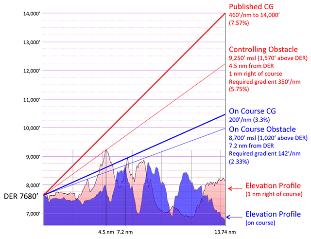
Aspen SARDD obstacle departure gradients
Reducing Climb Gradient Strategy by Required Obstacle Clearance (ROC) or Minimum Obstacle Clearance (MOC)
Since this departure procedure was designed using TERPS, one could argue that the 24 percent ROC can be removed in the event of an engine failure and the airplane would still have the net takeoff flight path.
- Loading your aircraft to the OEI numbers and the AEO climb gradient, your altitude over the 4.5 nm obstacle will be (4.5) (460) + 7680 = 9,750 feet.
- If you elect to load your aircraft so as to achieve 24 percent less climb, (1 - 0.24) (460) = 350 ft/nm, your altitude over the obstacle will be (4.5) (350) + 7680 = 9,255.
Just 5 feet vertical clearance! So will you cross the obstacle right at that altitude? No, remember your net takeoff flight path factor. A two-engine aircraft will actually be (.008) (4.5) (6076) = 219 feet above the obstacle. This is precisely the solution favored by some commercial vendors.
Another option would be to apply the smaller ICAO 0.8 percent MOC to the TERPS procedure. In our example, the aircraft would be loaded to provide for a climb gradient of 7.57 - 0.8 = 6.77 percent. You will cross the obstacle at (.0677) (4.5) (6076) + 7680 = 9,531 feet, 281 feet above the obstacle. Once you thrown in the net takeoff flight path factor, you clear the obstacle by 281 + 219 = 500 feet.
Commercial Options
You can easily compute your own reduced climb gradient by going through the charts and simply starting with a climb gradient reduced by the 24 percent ROC on a TERPS procedure or the 0.8 percent MOC on an ICAO procedure. You just need to be careful how you do that:
- On a TERPS procedure you multiply the published gradient by 0.76, making it 24 percent less. Our Aspen procedure goes from 460 ft/nm to (0.76) 460 = 350 ft/nm. (This equates to 350 / 6076 = 5.8%)
- On an ICAO procedure, you subtract 0.8 percent from the published gradient. A 7.6 percent gradient, for example, becomes 7.6 - 0.8 = 6.8 percent.
Pros
There are many advantages to reducing your obstacle climb gradient by the TERPS Required Obstacle Clearance (ROC) of 24 percent or the ICAO Minimum Obstacle Clearance (MOC) of 0.8 percent:
- Reducing the published gradient by the ROC or MOC still provides multi-engine aircraft with their 14 CFR 25.115 "net takeoff flight path" margin, which is 0.8 percent for two engine aircraft, 0.9 percent for three engine aircraft, and 1.0 percent for four engine aircraft.
- Using a software application can be more accurate than manually chasing a pencil through hard-to-use charts.
- Reducing the published gradient by the ROC or MOC will significantly increase the available payload for departure, and this can mean the difference between going or not going, or reaching one's destination or having to make a fuel stop.
Cons
The are also disadvantages:
- Reducing your climb gradient by the ROC or MOC leaves you only with the 14 CFR 25.115 "net takeoff flight path" as a safety margin, and that may not be enough if the winds change from a headwind on the runway to a tailwind at altitude, or if there is a temperature inversion. In our Aspen example, eliminating the 24 percent ROC reduces your margin over the first major obstacle from 500 feet to just 219 feet, the "net takeoff flight path" margin.
- Chasing through the spaghetti charts can induce critical errors that are large enough to eliminate the remaining safety margin. Using computer software can also be subject to errors, since it is up to the user to input the correct gradient. Available software does not include a database of the correct procedure gradients.
- This method does nothing to ensure low, close-in obstacles are addressed.
- It is up to you to ensure you can still meet the ODP climb gradient if you don't lose an engine; your AFM may not be of much help here. (I don't think this is really a problem but can't make that decision for you and your aircraft.
- The reduced gradient is still based on the wider lateral area of the obstacle departure procedure construction (TERPS or ICAO Doc 8168). The increase in payload is often insufficient to make a difference in a go / no-go decision.
Recommendation
I've used this method for many years after studying terrain charts and ensuring I fully understood where the threat was and even then, only if I had reasonable confidence the winds at altitude were not reversed. The best candidates were places in a large valley where I knew I would be able to navigate away from the terrain no matter the weather.
There was an accident many years ago, where an Air Force turboprop was unable to out-climb a mountain as result of a temperature inversion; so I added that to my list of things to worry about. Nevertheless, I continued to use the method until something better came along. And that leads us to . . .
A High Tech Strategy: A Terrain Data Base with Obstacle Analysis
We have already seen that reducing the vertical Obstacle Departure Procedure (ODP) climb gradient by the ICAO 0.8 percent Minimum Obstacle Clearance (MOC) or the TERPS 24 percent Required Obstacle Clearance (ROC) can pay dividends in allowing us to increase our payload while still providing adequate obstacle clearance in the event of an engine failure. (See above: "A low tech strategy - reduce the vertical margins.) But this approach proves worrisome because it requires a number of steps on a chart or with a piece of software that can subject to user errors and it doesn't address low, close-in obstacles.
We have also seen that the lateral clearances afforded by all TERPS and ICAO obstacle departure procedures is very generous and that if we are able to navigate to tighter tolerances we can eliminate consideration of some obstacles that could be as much as 3 nautical miles left or right of course centerline. If your airplane can navigate to tighter tolerances, you should be able to eliminate the far off obstacles and reduce your required climb gradient even further. You are permitted to do this in accordance with U.S. AC 120-91 and ICAO Annex 6, Part I, ATT C.
G450 Net gradient second segment climb
Let's go back to our Aspen example. Recall that using the The Old School Strategy we were limited to a takeoff grossweight of 48,227 lbs using the G450 FMS which automatically reduces the entered ODP climb gradient by the net takeoff flight path factor of 0.8 percent for a two-engine aircraft. Recall also that using the "Low tech strategy - reduce the vertical margins" we were able to reduce the climb gradient by the larger TERPS 24 percent ROC which yielded a much higher takeoff grossweight of 55,720 lbs. But this solution failed to address the low, close-in obstacle problem and retained the very wide lateral obstacle consideration inherent in any TERPS obstacle departure procedure. What if we could narrow the obstacle consideration zone to no more than the 3,000 feet lateral zone required by U.S.? Recall finally that the on-course obstacles were only at a gradient of 2.33 percent, substantially less than the 5.75 percent gradient just one mile right of course. That reduction to 2.33 percent makes a big difference.
For the purpose of illustration, if we assume there are no obstacles higher than those found on course within 3,000 feet left or right of course, we can chase through the chart to see our takeoff grossweight goes way up to over 70,000 lbs. I've done this only to illustrate the potential. It would take a very large database of all obstacles and a very capable computer to compare each of these to our route of flight to do the job properly. Fortunately there are commercial vendors who have just this capability.
Aircraft Performance Group (APG) "Runway Analysis" Services
Aircraft Performance Group offers what they call "Runway Analysis" to evaluate declared distances, runway slope, weather, and departure obstacles. Their services are available on web-based or stand alone applications and through many flight planning service providers. The departure obstacle analysis program plans for performance that avoids every obstacle laterally or vertically, including low, close-in obstacles. In the event of an engine failure the scheduled performance keeps you away from obstacles by required ICAO and U.S. FAA minimums. This method is not perfect, but it is nearly so.
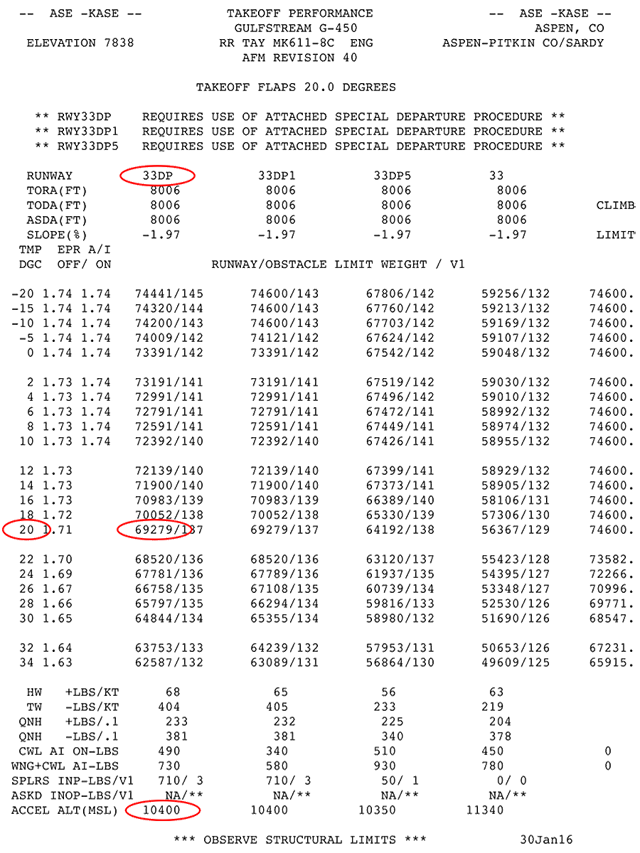
APG KASE data
Back to our Aspen example. Recall that using the "Low tech strategy: reduce the vertical margins," show above, we were able to reduce the obstacle departure procedure's climb gradient by the TERPS 24 percent ROC which yielded a much higher takeoff grossweight of 55,720 lbs. This gradient keeps us clear laterally of every obstacle in the very wide TERPS obstacle clearance area. The APG solution narrows our lateral obstacle distance to the 3,000 feet lateral zone required by U.S.AC 120-91 and produces OEI gross weights that are much higher.
The APG data shows we can depart under the same conditions at 69,279 lbs, slightly less than our attempt to manually derive on course obstacles. That makes sense because the APG data casts a wider net than our on course exercise. What about the "Requires use of attached special departure procedures" note attached to our selected 33DP column?
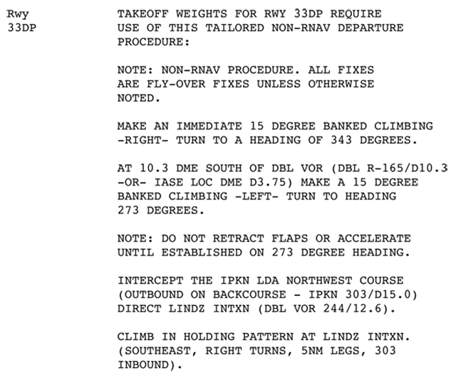
APG KASE special departure procedures 33DP
Reading the verbiage provided with the APG data, we see these instructions precisely mimic the SARDD THREE procedure. (Shown at the top of this page.) In fact, it is more precise, offering bank angles, a turn based on position and not altitude, and a specific time to begin flap retraction and acceleration. We can, as a result, have confidence that we can load our G450 to 69,279 lbs. and:
- be able to stay clear of all obstacles in the event of an engine failure if we stay within 3,000 feet of our filed and planned course,
- not have to worry about changing departure procedures in the event of an engine failure,
- be able to meet our obstacle departure procedure climb gradient if we don't have an engine failure (because we've checked the "double the thrust" theory in the simulator, see "Ensuring all-engine-operating (AEO) performance at higher weights.")
- have enough fuel to make it to our destination on the east coast, and
- avoid all low, close-in obstacles.
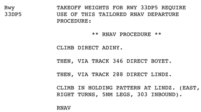
APG KASE special departure procedures 33DP5
Note, however, that there are more special procedures listed than just the DP1 that follows the ground track of the SARDD THREE . . .
It is unclear why you would select the special procedure 33DP5 other than, perhaps, being able to fly from waypoint to waypoint is appealing. This flight track is not duplicated by any of the airport's published procedures and it is doubtful you could file it as a matter of normal operations. I suppose that once you've lost the engine and declared an emergency you can fly any track you want and in some cases these APG hybrid procedures will result in further increased departure grossweight. (It does not in our Aspen example.) But if you plan using one of these unpublished procedures there is something you need to factor into the equation . . .
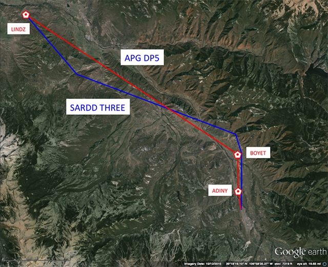
Comparing the procedures
The ground track of this procedure is different than the published SARDD THREE and you will not be able to file it for your planned departure. That leaves you in the situation where your FMS, ATC, and your departure briefing are all based on one thing (the SARDD THREE) and your plan in the event of an engine failure is another thing entirely. Are you going to have the presence of mind to make these changes after an engine failure? Even if all that is involved is changing the active flight plan in the FMS and making a radio call, you may have your hands full and this is just an unneeded nuisance.
Pros
There are many advantages to using a computer application that melds a digital obstacle file and terrain maps to narrow the obstacle clearance area with aircraft performance data to produce a climb gradient reduced by the TERPS Required Obstacle Clearance (ROC) of 24 percent or the ICAO Minimum Obstacle Clearance (MOC) of 8 percent:
- Reducing the published gradient by the ROC or MOC still provides multi-engine aircraft with their "net takeoff flight path" margins, which are 0.8 percent for two engine aircraft, 0.9 percent for three engine aircraft, and 1.0 percent for four engine aircraft.
- Narrowing the obstacle clearance area to no more than 3,000 feet laterally accounts for all obstacles the aircraft is likely to encounter with modern navigation capability.
- Accounting for all low, close-in obstacles allows the computed grossweight to out-climb these obstacles if possible, or identify needed procedures to avoid them laterally.
- Reducing the published gradient by the ROC or MOC and narrowing the obstacle clearance area will significantly increase the available payload for departure, and this can mean the difference between going or not going, or reaching one's destination or having to make a fuel stop.
Cons
The are two disadvantages that I can think of:
- Planning takeoff grossweight based on an unpublished procedure can introduce unwanted crew distractions when trying to quickly change FMS and other cockpit settings following an engine failure as well as the need to let ATC know your ground track is about to change. These procedures may have never been flight or simulator tested, unlike the published procedures.
- Pilots may not understand the mechanics involved when significantly increasing takeoff grossweight and how that impacts the margin of safety and increases the need to navigate more precisely. In our Aspen example we managed to increase our departure grossweight by almost 25 percent but cut our vertical clearance over the most restrictive obstacle by half. (An unexpected tailwind a few hundred feet in the air could erase that margin entirely.) Our lateral tolerance after the first two turns dropped from over 2 miles to less than a half of one mile.
Recommendation
I've been using APG data for over 10 years now and have had several issues, not the least of which are those unpublished procedures. But I've become comfortable using it and allow members of my flight department to use it provided they understand the trade-offs and follow the precautions which I am about the outline right now . . .
3
Recommendations
You can safely use all three of these methods, provided you take the right precautions and understand the trade-offs. My preference is as follows:
- The "High Tech Strategy" (terrain data base and obstacle analysis software) — I always default to running an APG analysis at any airport I am going to for the first time.
- If the resulting numbers default to the aircraft's maximum takeoff weight, I know there isn't an obstacle problem and I can then count on my aircraft's FMS performance computer to keep me safe. If the numbers are reduced because of obstacles, I use only published procedures and ensure I load my aircraft to a weight less than or equal to the APG stated limit.
- In either case, I know I've solved the low, close-in obstacle problem as well.
- I also check the weather to ensure there is no chance of a tailwind during the departure procedure or a significant temperature inversion.
- I will brief the crew that we are reducing our vertical and lateral safety margins and the need to navigate within a half-mile is critical. Because of this, we need to ensure our GPS RAIM is good, we need to set the RNP alert value on our avionics to 0.25 to give us ample warning if we are about to venture out of the 3,000 feet lateral protection area, and we need to do a check of all this just prior to takeoff.
- If I didn't have access to a program like APG's runway analysis, I would move on to the next option . . .
- The "Old School Strategy" (using one-engine-inoperative performance against the published all-engines-operative obstacle departure procedure) — My next choice would be to revert to using OEI performance against the AEO procedure with one extra allowance. If flying a TERPS procedure, I will allow the G450 performance computer's default 0.8 percent net takeoff flight path gradient reduction to determine a lower gradient. This gives me a little extra vertical margin. If I have reduced my vertical margin, I take the following precautions
- I will try to understand the low, close-in obstacle problem by studying the airport notes and if they are a threat, I will reduce my grossweight to a point that guarantees I will cross the DER at least 200' above the DER. That eliminates the problem.
- I also check the weather to ensure there is no chance of a tailwind during the departure procedure or a significant temperature inversion.
- I will brief the crew that we are flying with a reduced vertical margin. Because of this, we need to ensure our GPS RAIM is good, we need to set the RNP alert value on our avionics to 0.25 to give us ample warning if we are about to venture out of the 3,000 feet lateral protection area, and we need to do a check of all this just prior to takeoff.
- If I was flying an airplane without the G450's ability to automate this process, I would move on to the next option . . .
- The "Low Tech Strategy" (reducing the AEO departure procedure by the full value of 0.8 percent MOC on an ICAO procedure or 24 percent ROC on a TERPS procedure) — My last choice would be to use EFB-Pro because, in my opinion, the program is not user friendly (and that increases the chance of an input error) and requires the obstacle departure procedure be entered manually, introducing another opportunity for error. That being said, I would only use it on a TERPS procedure and then I would select the ICAO option to increase my vertical margin. From this point the precautions are identical to Option Two.
I've made these choices because APG is provided at no cost with our flight planning service provider (ARINCDirect) and the G450 has a very easy to use performance computer built into the normal performance and takeoff data pages of the FMS. If you have access to APG but your aircraft does not have a performance computer with this capability, you may opt to elevate the "low tech" strategy as your Option Two. I can't answer for you, but these are the choices I have made. No matter your choice, I recommend you understand what margins you are cutting (vertical and/or lateral), the need to navigate precisely and make the necessary GPS RAIM or other navigation accuracy checks, and keep an eye on winds and temperature at altitude. I've used these techniques for fifteen years now and they have often made the difference between being able to takeoff or having to wait for the weather to improve.
4
Gray Area
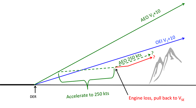
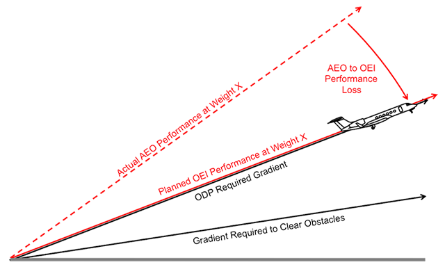
Obstacle clearance, three scenarios
We often think of gray areas as something with no right or wrong answer, but that isn't right. I think a gray area is more than likely a problem you haven't thought through. I often get asked "How can I be sure I'm going to clear an obstacle if I lose an engine after I've retracted my flaps and have accelerated above V2 to V2+10 when the charts are based on losing an engine at V1, climbing out with the flaps set at those speeds? It gets worse. What if you do all that and lose an engine after your flaps are up?
In the drawing there are four scenarios, two of which guarantee obstacle clearance and two which leave you with question marks:
- Blue line — If you load your airplane up to assure obstacle clearance One Engine Inoperative (OEI), climb with your flaps set as planned, and fly at the recommended speed (i.e., V2 to V2+10), you will be okay if you fly with the required precision.
- Green solid line — If you load your airplane up to assure obstacle clearance One Engine Inoperative (OEI) or All Engines Operating (AEO) using the appropriate planning, climb with your flaps set as planned, and fly at the recommended speed (i.e., V2 to V2+10), you will be okay if you fly with the required precision even if you lose an engine at any point from V1 all the way through obstacle clearance.
- Green dashed line — If you took the steps to assure obstacle clearance under scenarios 1 or 2 above, but after you takeoff decide you are going to accelerate above the target speed and clean up the airplane, you don't know if you are going to clear the obstacle, even if you don't lose an engine.
- Red line — If you took all the steps to assure obstacle clearance under scenarios 1 or 2 above, but after you takeoff decide you are going to accelerate above the target speed and clean up the airplane, and then you lose an engine, you are even more trouble. The best you can do is pull the nose up to catch the appropriate engine-out, flaps up speed (i.e., VSE). Even if you do this, you don't know if you are going to clear the obstacle.
This isn't so much a gray area as a pilot error in understanding what it takes to clear an obstacle. The only way to assure obstacle clearance is to fly the target speed in the correct configuration until the obstacles are cleared. Does that mean you need to subject your passengers to a rocket ship ride even if you don't lose an engine on the runway? Not necessarily. If you understand where the obstacles are you can adjust your clean up altitude appropriately.
In our Aspen example, above, we know the required climb gradient is dictated by two obstacles at 4.5 and 7.2 nm north of the airport, the higher of which is 9,250' MSL (1,570' above the departure end of the runway). We should plan on maintaining V2 to V2+10 until we've climbed above this altitude, even if we don't lose an engine. Now we know we can beat the obstacle following an engine failure at V1, at our planned level off altitude, or anywhere in between.
5
See and Avoid
When I started flying old turbojets with limited performance, beating the mountains with an engine failed was a constant worry. Our rules were simply to clear the obstacle with an engine out by any margin, what we called the "scrape paint" theory. One of the ways to do that was to simply spot the obstacle and avoid it. I hear this often as a civilian. The rationale goes like this: I can see the mountain. If I lose an engine I'll just turn the other way. Sometimes you don't see the mountain because there are so many of them that you don't know which one is the primary threat and you cannot avoid all of them. Sometimes the weather is technically okay but the visibility isn't as good as they say or it is dark. But even if you can see the obstacle, with an engine failed you might not have as much directional control as you need. In short, it might be legal but it might not be smart. I get questions about this now and then. Our "Legal Eagle," Chris Parker, put together a good answer.
Dear Team Code 7700,
A few of us have been having a friendly debate and wondering if you can answer the question. The scenario is as follows: Flying citations part 135 in the mountains in the summer. The example flight is out of EGE departing runway 25, weather is clear and a million, but a little warm. APG says we cannot make the custom alternate departure. I've heard the argument: "If we have an engine failure, we'll stay VFR and turn right to circle in the bowl to climb to a safe altitude." I've heard this debate before, whether or not "See and avoid" satisfies 135.379. I know what the safe conservative answer is, I'm curious what your thoughts are on whether or not this argument is legal.
An avid reader,
Dear Mr. Avid,
Thank you for your question. First, under 14 CFR Part 135 operations, large (aircraft of more than 12,500 lbs. maximum certificated takeoff weight), turbine-powered (turbojet and turboprop) airplanes must be operated under the performance rules in § 135.379 through § 135.387, as applicable (Subpart I of Part 135). Compliance with § 135.379 is mandatory on every takeoff; it does not matter if the airplane is operated under instrument flight rules (IFR) or visual flight rules (VFR) or if the weather conditions are instrument meteorological conditions (IMC) or visual meteorological conditions (VMC).
For at least the last 30 years and even today, and due partly to faulty training from Part 142 schools, misunderstandings within FAA inspector ranks, and lack of technically accurate training anywhere but in the 121 air carrier community, there persists a significant knowledge gap regarding takeoff planning and certification and operating rules with respect to one-engine inoperative (OEI) obstacle clearance requirements for operators of Part 25 aircraft.
A prevalent misunderstanding and misapplication of the rules is that an airplane with OEI must meet the required minimum climb gradient of a published standard instrument departure (SID) or obstacle departure procedure (ODP), when accepted as an element of an IFR ATC clearance. This is incorrect. IFR departure procedures assume AEO (all-engines operating) climb performance, and demonstrating that the airplane can meet these climb requirements after an engine failure is not required.
Yet there is another prevalent misunderstanding. Although an airplane with OEI is not legally required to meet the minimum climb gradient of a published SID or ODP, even if an airplane with OEI can meet the minimum climb gradient this still does not ensure terrain clearance (or §135.379 compliance) because U.S. terminal instrument procedures (TERPS) uses an uninterrupted surface defined by a gradient and Part 25 aircraft certification uses a segmented net takeoff flight path.
A special engine failure contingency procedure (or what you call a “custom alternate departure”) from a vendor such as Aircraft Performance Group (APG) may be an alternate acceptable means of compliance with the regulatory requirements of §135.379. These special engine failure contingency procedures may differ from the normal IFR departure procedure (e.g., SID or ODP) and are specifically designed as OEI “escape” procedures.
If conditions (takeoff weight, pressure altitude, outside air temperature, TODA) do not allow an airplane with OEI to meet the requirements of the special engine failure contingency procedure (“APG says we cannot make the custom alternate departure,” as in your example), an operator may use other methods to comply with the regulatory requirements of § 135.379 if those methods are shown to provide the necessary level of safety and are acceptable to the Federal Aviation Administration (FAA). (See: AC 120-91, ¶1, ¶21) Alternatively, an operator may reduce takeoff weight or depart when the outside air temperature is lower in order to meet the requirements of the special engine failure contingency procedure.
Principal Operations Inspectors (POIs) of Part 135 certificate holders are tasked with ensuring that each certificate holder's manual system (e.g., General Operations Manual, GOM) contains procedures that ensure compliance with applicable Part 135 Subpart I performance requirements. In other words, the use of the APG special engine failure contingency procedure must be specifically described and published in your GOM, which is an “FAA accepted document.” There should also be appropriate training (ideally in the simulator) on how to accomplish these alternate procedures. POIs and training center program managers (TCPMs) should ensure that appropriate takeoff emergency situational training is accomplished covering at least the following items:
1) Training to ensure that if an engine fails on takeoff in an airplane, a pilot shall avoid obstacles following the OEI contingency procedure developed by the operator.
2) Emphasis on pilots accomplishing immediate action items.
3) Declaring an emergency with ATC as soon as practicable.
4) Ensuring crews advise ATC of their intentions to fly the OEI routing developed during planning.
NOTE: Inspectors are to ensure that operators/pilots understand the IFR departure procedure is then no longer applicable, and ATC must assist as necessary for the emergency.
Without a doubt, the determination that safe takeoff obstacle clearance can be achieved following an engine failure on takeoff is not an easy task. Your Chief Pilot or Director of Operations can tell you if your GOM authorizes you to perform this assessment before each takeoff (e.g., "If we have an engine failure, we'll stay VFR and turn right to circle in the bowl to climb to a safe altitude.") Before you accept this responsibility, ask yourself if you possess the training, the tools, and the skills to analyze the engine out performance of your airplane. Can you determine where all the critical obstacles are along your takeoff path for every takeoff? (Including low, close-in obstacles not accounted for by TERPS criteria?) And do you have the tools necessary to calculate a takeoff weight that will clear these critical obstacles?
If the answer is maybe, no, or I don’t know to any of these questions, then you may want to consider using a special engine failure contingency procedure to comply with § 135.379. In any case, under FAR Part 135, you must be authorized to use any alternate method. (I would recommend getting this authorization in writing if not published in your GOM.) I doubt the phrase: "If we have an engine failure, we'll stay VFR and turn right to circle in the bowl to climb to a safe altitude" would be an acceptable means of compliance with § 135.379 and accepted by your POI as providing the necessary level of safety. Just as I doubt it would be an acceptable means of compliance for American Airlines, who flies Airbus 319s into and out of KEGE, or Skywest Airlines, who flies Embraer E-170s and E-175s into and out of KEGE. You can bet those airlines have published OEI guidance for their crews and those crews are trained in those procedures. Remember, Part 135 rules were designed to provide an equivalent level of safety as Part 121 rules for paying passengers.
I hope this information has been helpful and responsive to your question.
Sincerely,
Chris Parker
Code7700.com
References:
Transport Airplane Performance Working Group Video (Part 1 of 4): Planning for Takeoff Obstacle Clearance (youtube.com)
Transport Airplane Performance Planning Group/ACF/AFS410, Primary Part 25 Performance Subjects, Bruce McGray, FAA AFS-410, Sept 15, 2015 accessed here: https://www.faa.gov/air_traffic/flight_info/aeronav/acf/media/Presentations/15-02_TAPP_presentation_McGray.pdf
FAA Order 8900.1 Flight Standards Information Management System (current)
Advisory Circular 120-91, Airport Obstacle Analysis (current)
14 CFR Part 135 (current)
14 CFR Part 91 (current)
FAA-H-8083-15B, Instrument Flying Handbook (current)
NBAA “One Engine Inoperative Takeoff Planning and Climb Performance” Steve Leon, May 10, 2012, accessed here: https://nbaa.org/aircraft-operations/safety/in-flight-safety/aircraft-climb-performance/one-engine-inoperative-takeoff-planning-and-climb-performance/
References
(Source material)
14 CFR 25, Title 14: Aeronautics and Space, Airworthiness Standards: Transport Category Airplanes, Federal Aviation Administration, Department of Transportation
14 CFR 91, Title 14: Aeronautics and Space, General Operating and Flight Rules, Federal Aviation Administration, Department of Transportation
14 CFR 121, Title 14: Aeronautics and Space, Operating Requirements: Domestic, Flag, and Supplemental Operations, Federal Aviation Administration, Department of Transportation
14 CFR 135, Title 14: Aeronautics and Space, Operating Requirements: Commuter and On Demand Operations and Rules Governing Persons on Board Such Aircraft, Federal Aviation Administration, Department of Transportation
14 CFR 139, Title 14: Aeronautics and Space, Certification of Airports
Advisory Circular 120-91, Airport Obstacle Analysis, 5/5/06, U.S. Department of Transportation
Aeronautical Information Manual
Bombardier BD-700-1A10 Airplane Flight Manual, Rev 80, Jun 03/2014.
Gulfstream G450 Airplane Flight Manual, Revision 36, December 5, 2013
ICAO Annex 6 - Operation of Aircraft - Part 1 Commercial Aircraft, International Standards and Recommended Practices, Annex 6 to the Convention on International Civil Aviation, Part I, July 2010
ICAO Annex 8 - Airworthiness of Aircraft, International Standards and Recommended Practices, Annex 8 to the Convention on International Civil Aviation, July 2010
ICAO Doc 8168 - Aircraft Operations - Vol II - Construction of Visual and Instrument Flight Procedures, Procedures for Air Navigation Services, International Civil Aviation Organization, 2006
United States Standard for Terminal Instrument Procedures (TERPS), Federal Aviation Administration 8260.3B CHG 25, 03/09/2012
Please note: I've used some Gulfstream performance charts for the purposes of education. Gulfstream Aerospace Corporation has no affiliation or connection whatsoever with this website, and Gulfstream does not review, endorse, or approve any of the content included on the site. As a result, Gulfstream is not responsible or liable for your use of any materials or information obtained from this site.