I was attending an Air Force instrument school refresher back in 1982 when the instructor was giving each pilot a holding problem that ended with, "which way do you turn?" He asked the fighter pilot sitting to my left who said, "I would declare an emergency." When asked why he would do that, the pilot said, "Real pilots don't hold."
— James Albright

Updated:
2022-12-13
Well, not only do real pilots hold, we hold all over the world and the rules are not universal. If you apply U.S. FAA rules outside our borders, you could find yourself in a bit of trouble. There are, thankfully, techniques to keep you on the right side of the law.
1
Instructions
The rules that follow appear to be unique to the U.S. FAA.
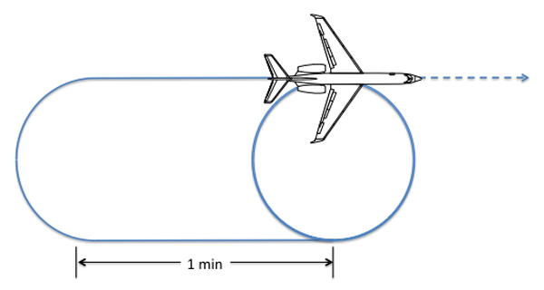
Standard Holding Pattern
Standard Holding Pattern, from FAA-H-8083-15, page 10-10.
The standard pattern is a racetrack pattern with 180° turns to the right and one minute legs. Pilots are expected to compensate for the effect of a known wind except when turning and to adjust outbound timing so as to achieve a 1-minute (1-1/2 minutes above 14,000 feet) inbound leg.
Source: FAA-H-8083-15, Figure 10.4
A "standard pattern" has right turns and a "nonstandard pattern" has left turns.
Source: Aeronautical Information Manual §5-3-8 ¶j.1.
No Holding Instructions Given
If you arrive at your clearance limit before receiving clearance beyond the fix, ATC expects you to maintain the last assigned altitude and begin holding in accordance with the depicted holding pattern. If no holding pattern is depicted, you are expected to begin holding in a standard holding pattern on the course upon which you approached the fix.
Source: FAA-H-8083-15, page 10-11
If the holding pattern is charted and the controller doesn't issue complete holding instructions, the pilot is expected to hold as depicted on the appropriate chart.
Source: Aeronautical Information Manual §5-3-8.b.
Holding Instructions Given, Fix Undepicted
Where a holding pattern is not depicted, the ATC clearance will specify the following:
- Direction of holding from the fix in terms of the eight cardinal compass points (i.e., N, NE, E, SE, etc.).
- Holding fix (the fix may be omitted if included at the beginning of the transmission as the clearance limit).
- Radial, course, bearing, airway, or route on which the aircraft is to hold.
- Leg length in miles if DME or area navigation (RNAV) is to be used (leg length will be specified in minutes on pilot request or if the controller considers it necessary).
- Direction of turn if left turns are to be made, the pilot requests or the controller considers it necessary.
- Time to expect-further-clearance (EFC) and any pertinent additional delay information.
Source: FAA-H-8083-15, page 10-11, Aeronautical Information Manual §5-3-8.i.
Some pilots use what might be called "the wind arrow" method of drawing these undepicted holding patterns. I've always found it more useful to simply write the instructions down as given, but others swear by this method. You draw the pattern as the instructions are given. For example: (All diagrams from my notes.)
"Hold northwest"
As soon as you hear this first part of the instruction, draw a wind arrow from the direction given. In this case, we draw an arrow FROM the northwest.
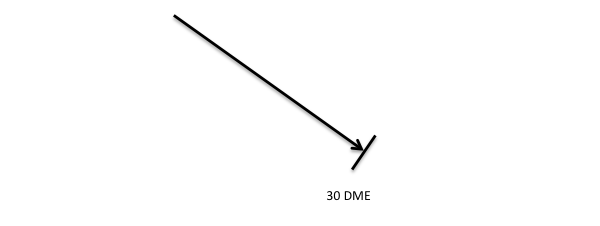
"of the 30 DME fix, Austin VORTAC,"
If you are given a fix, you can place it at the arrowhead. You might also be given a navaid or a named fix, which can also be placed at the arrowhead. In this case, we place a 30 DME fix at the arrowhead.
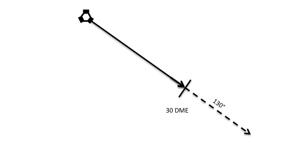
"130 radial,"
You will be typically given a radial, in which case the Navaid goes at the tail of the arrow. While not common, you might also be given a course, in which case the Navaid goes at the head of the arrow.
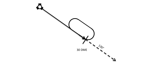
"10-mile legs, left turns."
When given the length of the pattern you must still wait to hear if "left turns" is given. If it isn't then the turns will be to the right. In any case, you have to wait until the end of the instruction to make this determination. In this case, we draw the pattern to the left.
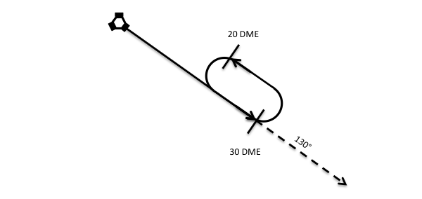
Once we've drawn the pattern on the correct side, adding the leg distance comes next.
G450 Note
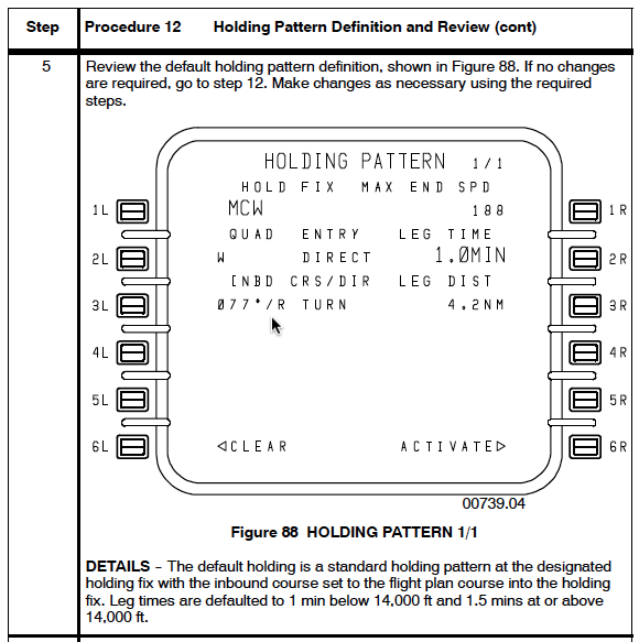
G450 Holding Pattern Definition, from G450 Aircraft Operating Manual §2B-27-00, page 97.
One of the selling points for G450 Enhanced Navigation systems is that FMS holding patterns, en route and approach, are smarter. They are, we have been told, the published procedures. Well, that generally works but that isn't what the manual says. I have found errors over the years. If given "hold as published," I punch in the FMS holding pattern to get me started and then I hunt for the pattern first on the DU charts and then going through en route paper charts. If I can't find the published procedure, I ask. The G450 FMS is good, but it isn't perfect.
2
Entry procedures
The U.S. and ICAO holding pattern sectors are identical, but the terminology is slightly different. The entry procedures under ICAO not as flexible as under U.S. rules and there are several special cases involving DME arcs and VOR radials.
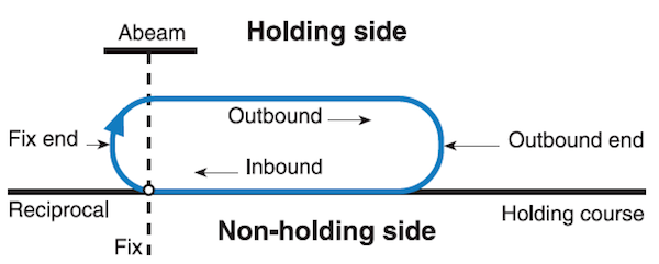
Holding Pattern Shape and Terminology
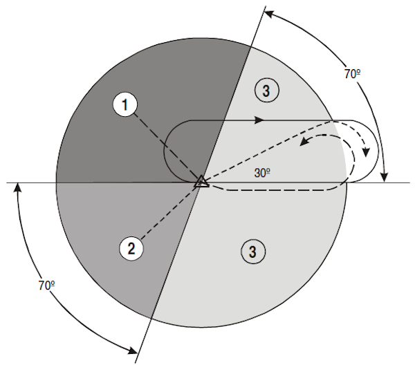
Entry sectors, from ICAO Doc 8168 Vol 1, Figure I-6-1-2.
- ICAO: Sector 1 (Parallel entry)
U.S. FAA: Parallel - ICAO: Sector 2 (Offset entry)
U.S. FAA: Teardrop - ICAO: Sector 3 (Direct entry)
U.S. FAA: Direct
Sector 1 (Parallel) Entry
U.S. FAA
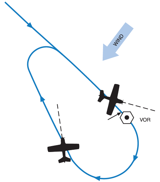
When approaching the holding fix from anywhere in the parallel sector, turn to a heading to parallel the holding course outbound on the non holding side for approximately 1 minute, turn in the direction of the holding pattern through more than 180°, and return to the holding fix or intercept the holding course inbound.
Source: Aeronautical Information Manual §5-3-8 ¶3.(a)
ICAO
- at the fix, the aircraft is turned left onto an outbound heading for the appropriate period of time; then
- the aircraft is turned left onto the holding side to intercept the inbound track or to return to the fix; and then
- on second arrival over the holding fix, the aircraft is turned right to follow the holding pattern.
Source: ICAO Doc 8168 Vol 1 §6 ¶ 1.4.4
Sector 2 (Offset) Entry
U.S. FAA
When approaching the holding fix from anywhere in the teardrop sector, fly to the fix, turn outbound using course guidance when available, or to a heading for a 30° teardrop entry within the pattern (on the holding side) for approximately 1 minute, then turn in the direction of the holding pattern to intercept the inbound holding course.
Source: Aeronautical Information Manual §5-3-8 ¶3.(b)
ICAO
- at the fix, the aircraft is turned onto a heading to make good a track making an angle of 30° from the reciprocal of the inbound track on the holding side; then
- the aircraft will fly outbound:
- for the appropriate period of time where timing is specified; or
- until the appropriate limiting DME distance is reached, where distance is specified. If a limiting radial is also specified, then the outbound distance is determined either by the limiting DME distance or the limiting radial, whichever comes first;
- the aircraft is turned right to intercept the inbound holding track; and
- on second arrival over the holding fix, the aircraft is turned right to follow the holding pattern.
Source: ICAO Doc 8168 Vol 1 §6 ¶ 1.4.5
Sector 3 (Direct) Entry
U.S. FAA
When approaching the holding fix from anywhere in the direct entry sector, fly directly to the fix and turn to follow the holding pattern.
Source: Aeronautical Information Manual §5-3-8 ¶3.(c)
ICAO
Having reached the fix, the aircraft is turned right to follow the holding pattern.
Source: ICAO Doc 8168 Vol 1 §6 ¶ 1.4.6
DME Arc Entry Holding (ICAO)
At the fix, the aircraft shall enter the holding pattern in accordance with either Sector 1 or Sector 3 entry procedure.
Source: ICAO Doc 8168 Vol 1 §6 ¶ 1.4.7
Special Entry Procedure for VOR/DME Holding (ICAO)
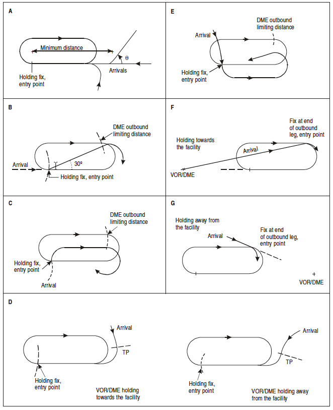
VOR/DME holding entry procedures, from ICAO Doc 8168 Vol 1 figure I-6-1-3.
Where a special entry procedure is used, the entry radial is clearly depicted.
Source: ICAO Doc 8168 Vol 1 §6 ¶ 1.4.8
Course Reversals versus Procedure Turns
The U.S. Procedure Turn can often be thought of as a holding pattern, in fact some are called "holding patterns in lieu of procedure turns." This is not true under ICAO: the entry procedures are different and the patterns themselves are varied and cannot normally be substituted one for the other.
These procedures are spelled out here: Course Reversals.
3
Speed
If you use 200 knots below 6,000 feet; 220 knots below 14,000 feet; and 240 knots above that, you will stay within PANS OPS 3 and 4 limitations and all other international holding speed limitations. But don't forget your aircraft's stall speeds go up as the altitude goes up: The Impact of High Altitude.
See Course Reversals for more information.
U.S. FAA
Reduce to holding speed when within 3 minutes of the holding fix. Maximum permitted speed is:
- 200 KIAS (when 6,000 feet and below),
- 230 KIAS (when 6,001 - 14,000 feet),
- 265 KIAS (when 14,001 feet and above).
Source: FAA-H-8083-15, page 10-11
When an aircraft is 3 minutes or less from a clearance limit and a clearance beyond the fix has not been received, the pilot is expected to start a speed reduction so that the aircraft will cross the fix, initially, at or below the maximum holding speed.
Source: Aeronautical Information Manual §5-3-8.d.
ICAO
Holding patterns shall be entered and flown at or below the airspeeds given:
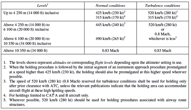
Holding speeds, from ICAO Doc 8168 Vol 1 Figure I-6-1-1.
Source: ICAO Doc 8168 Vol 1 §6 ¶ 1.3.1
4
Bank angle / rate of turn
25 degrees of bank with your flight director works well everywhere.
U.S. FAA
Make all turns during entry and while holding at:
- 3 degrees per second
- 30 degrees of bank
- 25 degrees bank provided a flight director system is used
Note: use whichever requires the least bank angle.
Source: Aeronautical Information Manual §5-3-8 ¶ 6(b
ICAO
All turns are to be made at a bank angle of 25° or at a rate of 3° per second, whichever requires the lesser bank.
Source: ICAO Doc 8168 Vol 1 §6 ¶ 1.3.2
5
Allowance for known wind
The U.S. allows "double drift" and "triple drift" techniques, the ICAO does not.
U.S. FAA
Drift correction in a holding pattern, from FAA-H-8083-15 Figure 10-5.
Compensate for wind effect primarily by drift correction on the inbound and outbound legs. When outbound, triple the inbound drift correction to avoid major turning adjustments.
Source: Aeronautical Information Manual §5-3-8 ¶ 6(c)
These techniques are important when flying low speed aircraft where the relative velocity of the crosswind can be significant, but less so for a higher speed aircraft. Nonetheless, they remain valid techniques for any aircraft in U.S. airspace.
ICAO
All procedures depict tracks. Pilots should attempt to maintain the track by making allowance for known wind by applying corrections both to heading and timing. This should be done during entry and while flying in the holding pattern.
Source: ICAO Doc 8168 Vol 1 §6 ¶ 1.3.3
The ICAO does not specify double or triple drift techniques, but they don't specifically forbid them either. A triple drift, it should be noted, could place the airplane outside of protected airspace.
6
EFC timing
Start of Outbound Timing
U.S. FAA
Outbound leg timing begins over/abeam the fix, whichever occurs later. If the abeam position cannot be determined, start timing when turn to outbound is completed.
Source: Aeronautical Information Manual §5-3-8 ¶4.(b)
ICAO
Outbound timing begins over or abeam the fix, whichever occurs later. IF the abeam position cannot be determined, start timing when the turn to outbound is completed.
Source: ICAO Doc 8168 Vol 1 §6 ¶ 1.3.4
Timing
U.S. FAA
The initial inbound leg should be flown for 1 minute (at or below 14,000 feet MSL) or 1-1/2 minutes (above 14,000 feet MSL). Timing for subsequent outbound legs should be adjusted, as necessary, to achieve proper inbound leg time.
Source: Aeronautical Information Manual §5-3-8 ¶4
ICAO
The still air timing for flying the outbound entry heading should not exceed:
- one minute if at or below 4,250 m (14,000 ft); or
- one and one-half minutes if above 4,250 m (14,000 ft).
Where DME is available, the length of the outbound leg may be specified in terms of distance instead of time.
Source: ICAO Doc 8168 Vol 1 §6 ¶ 1.4.9
Timing Technique
With slower aircraft you could vary your bank angle to produce standard rate and half standard rate turns to give known times for 360° circles, making time adjustments for an EFC easy. With higher speed aircraft you don't have that option, since a half-standard rate turn could place you outside protected airspace and a standard rate turn could exceed the 25° bank angle limit. Given these complications, you should do the following during your first trip around the holding pattern:
- Enter the holding pattern at your planned holding speed.
- Start timing as you begin your first 180° turn, stop timing as your roll out.
- Double this time to establish your time to make a 360° turn.
- You can adjust outbound leg timing to nail the EFC, example follows.
- If you adjust your speed as the holding continues, time the next turn to establish a new 360° time.
EFC Example
Holding pattern timing
Let's say you have an EFC of 1030Z and have entered the holding pattern at your desired speed. You time your first turn and come up with 1 minute, 15 seconds which means your 360° time is 2 minutes, 30 seconds.
On your next circuit you roll wings level outbound at 1015Z, 15 minutes to go. Since you know each circuit takes 4 minutes, 30 seconds (two 1-minute legs plus the 2 minute, 30 second 360°), you can kill the 15 minutes using two full circuits (9 minutes) and two partial circuits of 3 minutes each. How do you do that? A 360° circle takes 2 minutes, 30 seconds, so put a 15 second straight leg on each side:
- 4:30 — First full circuit: 1 minute outbound, 1:15 turn, 1 minute inbound, 1:15 turn
- 4:30 — Second full circuit: 1 minute outbound, 1:15 turn, 1 minute inbound, 1:15 turn
- 3:00 — First partial circuit: 15 seconds outbound, 1:15 turn, 15 seconds inbound, 1:15 turn
- 3:00 — Second partial circuit: 15 seconds outbound, 1:15 turn, 15 seconds inbound, 1:15 turn
7
The impact of high wind
Many of us flying aircraft with narrow weight ranges think of a single holding speed and forget that it will need to be increased with altitude. In heavier iron, that fact becomes obvious, but we can forget when our initial planned altitude is increased. The impact of bank angle can make what seemed okay, less so. The following is offered verbatim from a March 27, 2019 article in the World of Aviation.
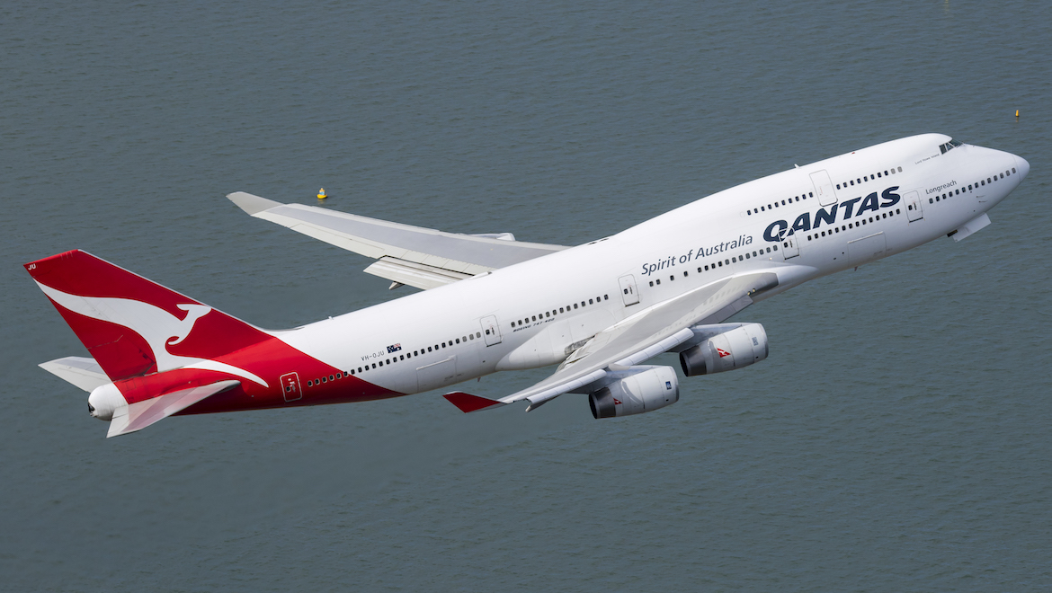
Qantas Boeing 747-400 VH-OJU (Seth Jarworski)
Qantas has retrained its pilots for some stall recovery techniques following a “stick shaker” incident on a Boeing 747-400 prior to landing in Hong Kong, the Australian Transport Safety Bureau (ATSB) says.
The incident occurred on April 7 2017, when VH-OJU was operating the QF29 from Melbourne to Hong Kong with 17 cabin crew and 347 passengers on board.
The ATSB final report published on Wednesday said that the aircraft’s aerodynamic stall warning stick shaker activated as the aircraft entered a holding pattern above a waypoint BETTY.
This led to multiple oscillations of pitch angle and vertical acceleration. During the event, passengers and cabin crewmembers struck the cabin ceiling and furnishings.
The ATSB investigation found that the flight crew, comprising the Captain as pilot flying and First Officer as pilot monitoring as well as a Second Officer, had anticipated being asked to hold between 15,000ft and 16,000ft (FL 150 to FL 160) and had used the flight management computer (FMC) to plan for this to occur.
As such, the Captain asked the First Officer to input 225kt above FL 150 as the target hold speed.
However, as the aircraft approached waypoint BETTY at FL 230, air traffic control instructed the flight crew to descend to FL 220 and hold at that attitude.
An altitude of 22,000ft was then entered in the autopilot altitude selection window.
“However, the flight crew did not adjust the target hold speed in alignment with the higher-than-expected hold level,” the ATSB final report said.
“The flight crew later reported that they were not aware of a higher speed requirement for holding above FL 200.”
The wind conditions and approximate track of Qantas Boeing 747-400 VH-OJU before landing at Hong Kong. (ATSB)The wind conditions and approximate track of Qantas Boeing 747-400 VH-OJU before landing at Hong Kong. (ATSB)
The ATSB final report said the aircraft’s speed reduced below both the target speed of 225kt and the minimum manoeuvring speed, which was indicated on the pilot’s flight display (PFD), as it was descending towards BETTY.
This was not noticed by the Captain or First Officer as the Captain was reviewing the Hong Kong approach documentation and the First Officer was looking out to the right of the aircraft in an attempt to identify aircraft traffic in the vicinity of the holding pattern.
Meanwhile, the Second Officer said he had observed the speed reducing close to but not below the 225kt selected.
When the 747-400 began a right turn to enter the holding pattern, it descended through FL 222 and reached a bank angle of a maximum of 32 degrees.
Three seconds after the aircraft began a right turn to enter the holding pattern, the aircraft began experiencing “pre-aerodynamic stall buffeting” as its bank angle increased to a maximum of 32 degrees and speed reduced to 220kt.
In response to the buffeting, the autopilot was disconnected and the Captain pushed forward on the control column to reduce the aircraft’s pitch angle bank angle.
“Due to a desire to remain within the protected airspace of the holding pattern, the captain did not roll to wings level as recommended by the operator’s approach to stall recovery procedure,” the ATSB final report said.
“The captain also did not disconnect the autothrottle as required by the procedure, however, he manually advanced the thrust levers.”
“The first officer observed the captain’s actions and was satisfied that the appropriate actions had been undertaken. He did not identify, and therefore did not callout, that the stall recovery procedure had not been completed.”
The buffeting then stopped and the aircraft continued descending.
However, the aircraft’s stick shaker warning activated twice as the Captain sought to increase the pitch angle to prevent further descent.
During the oscillations in altitude, five cabin crew members struck the cabin ceiling, with three suffering injuries.
A passenger that was in a restroom suffered minor injuries when he struck the cabin ceiling. A second passenger, who did not have her seatbelt fastened, was also injured.
The locations of the injured cabin crew members and injured passengers on the flight. (ATSB)The locations of the injured cabin crew members and injured passengers on the flight. (ATSB)
The ATSB report said Qantas had provided flight crew with limited training and guidance relating to the need for crew to re-evaluate their holding speed for a change in altitude, specifically above flight level 200.
In response to the incident, the ATSB said Qantas had updated flight crew training lesson plans and commenced retraining of flight crew in more complex stall recovery events.
Further, Qantas had also amended the 747-400, 787 and 737 flight crew training manuals and updated flight crew ground school lesson plans to ensure standardisation of training.
Separately, Qantas fleet safety Captain Debbie Slade noted the ATSB final report showed the three pilots were managing a number of tasks simultaneously when asked to enter a holding pattern over Hong Kong when preparing to land.
“There was a mismatch between the holding speed and altitude entered into the flight management computer, which the crew was alerted to by one of several safeguards on the flight deck,” Captain Slade said in a statement following publication of the ATSB final report on Wednesday.
“In correcting the aircraft’s path, the crew was very conscious they were operating in congested airspace and had limited room to manoeuvre, which added to the sense of turbulence in the cabin.”
“We take these incidents very seriously and use them as an opportunity to reinforce procedures and improve safety.”
Qantas said its pilots went through four recurrent simulator training sessions every year.
ATSB executive director for transport safety Nat Nagy said: “Balancing competing attention or decision demands can interrupt trained flight crew responses leading to procedures not being completed in full, particularly so if flight crews are not receiving comprehensive and regular training in the application of these skills.”
“Comprehensive theory and practical training can ensure that flight crews have a complete understanding of aircraft systems and maintain effective manual handling skills. This training should provide the knowledge to correctly configure the aircraft’s automatic flight systems and manual handling skills to respond adequately to in-flight upsets.”
References
(Source material)
Aeronautical Information Manual
ATSB Releases Final Report on Qantas 747 "Stick Shaker" Incident, World of Aviation, March 27, 2019
FAA-H-8083-15, Instrument Flying Handbook, U.S. Department of Transportation, Flight Standards Service, 2001.
Gulfstream G450 Aircraft Operating Manual, Revision 35, April 30, 2013.
ICAO Doc 8168 - Aircraft Operations - Vol I - Flight Procedures, Procedures for Air Navigation Services, International Civil Aviation Organization, 2006
Please note: Gulfstream Aerospace Corporation has no affiliation or connection whatsoever with this website, and Gulfstream does not review, endorse, or approve any of the content included on the site. As a result, Gulfstream is not responsible or liable for your use of any materials or information obtained from this site.