The Instrument Landing System is fantastic, except when someone drives through the antenna beam. Then? Not to fantastic. But it is still the approach of choice just about everywhere in the world.
— James Albright

Updated:
2022-12-23
The beauty of the ILS is how simple it is to fly, once you get the hang of it. But that can be a problem because we can get away with flying them for years without understanding the magic behind the curtain, and how to detect when the magic goes wrong.

1
General description
Plus the regulatory and equipment requirements
General Description
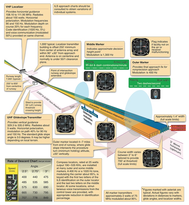
FAA-H-8083-15B, Instrument Flying Handbook, Figure 9-33.
Instrument landing system (ILS): An electronic system that provides both horizontal and vertical guidance to a specific runway, used to execute a precision instrument approach procedure. The ILS system provides both course and altitude guidance to a specific runway. The ILS system is used to execute a precision instrument approach procedure or precision approach. The system consists of the following components:
- A localizer provides horizontal (left/right) guidance along the extended centerline of the runway.
- A glide slope provides vertical (up/down) guidance toward the runway touchdown point, usually at a 3° slope.
- Marker beacons provide range information along the approach path.
- Approach lights assist in the transition from instrument to visual flight.
Source: FAA-H-8083-15B, Instrument Flying Handbook, pg. 9-35
Equipment Requirements
FAA-H-8083-15B, Instrument Flying Handbook,
Figure 9-36.
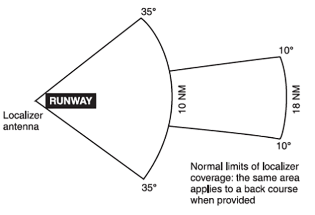
- Localizer. The localizer (LOC) ground antenna array is located on the extended centerline of the instrument runway of an airport, remote enough from the opposite (approach) end of the runway to prevent it from being a collision hazard. This unit radiates a field pattern, which develops a course down the centerline of the runway toward the middle markers (MMs) and outer markers (OMs), and a similar course along the runway centerline in the opposite direction. These are called the front and back courses, respectively. The localizer provides course guidance, transmitted at 108.1 to 111.95 MHz (odd tenths only), throughout the descent path to the runway threshold from a distance of 18 NM from the antenna to an altitude of 4,500 feet above the elevation of the antenna site.
- The localizer course is very narrow, normally 5°. This results in high needle sensitivity. With this course width, a full-scale deflection shows when the aircraft is 2.5° to either side of the centerline. This sensitivity permits accurate orientation to the landing runway. With no more than one-quarter scale deflection maintained, the aircraft will be aligned with the runway.
- Glide Slope. Glide slope (GS) describes the systems that generate, receive, and indicate the ground facility radiation pattern. The glide path is the straight, sloped line the aircraft should fly in its descent from where the glide slope intersects the altitude used for approaching the FAF, to the runway touchdown zone.
- The glide-slope equipment is housed in a building approximately 750 to 1,250 feet down the runway from the approach end of the runway, and between 400 and 600 feet to one side of the centerline.
- The course projected by the glide-slope equipment is essentially the same as would be generated by a localizer operating on its side. The glide-slope projection angle is normally adjusted to 2.5° to 3.5° above horizontal, so it intersects the MM at about 200 feet and the OM at about 1,400 feet above the runway elevation. At locations where standard minimum obstruction clearance cannot be obtained with the normal maximum glide-slope angle, the glide-slope equipment is displaced farther from the approach end of the runway if the length of the runway permits; or, the glideslope angle may be increased up to 4°.
- Unlike the localizer, the glide-slope transmitter radiates signals only in the direction of the final approach on the front course. The system provides no vertical guidance for approaches on the back course. The glide path is normally 1.4° thick. At 10 NM from the point of touchdown, this represents a vertical distance of approximately 1,500 feet, narrowing to a few feet at touchdown.
- Marker Beacons. Two VHF marker beacons, outer and middle, are normally used in the ILS system. A third beacon, the inner, is used where Category II operations are certified. A marker beacon may also be installed to indicate the FAF on the ILS back course.
- The OM is located on the localizer front course 4 to 7 miles from the airport to indicate a position at which an aircraft, at the appropriate altitude on the localizer course, will intercept the glide path The MM is located approximately 3,500 feet from the landing threshold on the centerline of the localizer front course at a position where the glide-slope centerline is about 200 feet above the touchdown zone elevation. The inner marker (IM), where installed, is located on the front course between the MM and the landing threshold. It indicates the point at which an aircraft is at the decision height on the glide path during a Category II ILS approach. The back-course marker, where installed, indicates the back-course FAF.
- Compass Locator. Compass locators are low-powered NDBs and are received and indicated by the ADF receiver. When used in conjunction with an ILS front course, the compass locator facilities are collocated with the outer and/or MM facilities. The coding identification of the outer locator consists of the first two letters of the three-letter identifier of the associated LOC. For example, the outer locator at Dallas/Love Field (DAL) is identified as “DA.” The middle locator at DAL is identified by the last two letters “AL.”
- Approach Lighting Systems (ALS). Normal approach and letdown on the ILS is divided into two distinct stages: the instrument approach stage using only radio guidance, and the visual stage, when visual contact with the ground runway environment is necessary for accuracy and safety. The most critical period of an instrument approach, particularly during low ceiling/visibility conditions, is the point at which the pilot must decide whether to land or execute a missed approach. As the runway threshold is approached, the visual glide path will separate into individual lights. At this point, the approach should be continued by reference to the runway touchdown zone markers. The ALS provides lights that will penetrate the atmosphere far enough from touchdown to give directional, distance, and glide path information for safe visual transition.
Source: FAA-H-8083-15B, Instrument Flying Handbook, pg. 9-35
More about: Approach Lighting Systems (ALS).
Regulatory Requirements
Categories of instrument approach procedures allowed at airports equipped with the following types of instrument landing systems:
- ILS Category I: Provides for approach to a height above touchdown of not less than 200 feet, and with runway visual range of not less than 1,800 feet.
- ILS Category II: Provides for approach to a height above touchdown of not less than 100 feet, and with runway visual range of not less than 1,200 feet.
- ILS Category IIIA: Provides for approach without a decision height minimum and with runway visual range of not less than 700 feet.
- ILS Category IIIB: Provides for approach without a decision height minimum and with runway visual range of not less than 150 feet.
- ILS Category IIIC: Provides for approach without a decision height minimum and without runway visual range minimum.
Source: FAA-H-8083-15B, Instrument Flying Handbook, pg. G-9
All you need to fly a Category I ILS approach, besides the aircraft and ground equipment, is an instrument rating. If you want to go for a higher category, you will have increased aircraft maintenance requirements, a few training hoops to jump through, and you will need some form of authorization. See FAA Order 8900.1, Volume 4, Chapter 2.
2
Limitations
Plus a summary of advantages and disadvantages
Limitations
The ILS and its components are subject to certain errors, which are listed below. Localizer and glide-slope signals are subject to the same type of bounce from hard objects as space waves.
- Reflection. Surface vehicles and even other aircraft flying below 5,000 feet above ground level (AGL) may disturb the signal for aircraft on the approach.
- False courses. In addition to the desired course, glideslope facilities inherently produce additional courses at higher vertical angles. The angle of the lowest of these false courses will occur at approximately 9°–12°. An aircraft flying the LOC/glide-slope course at a constant altitude would observe gyrations of both the glide-slope needle and glide-slope warning flag as the aircraft passed through the various false courses. Getting established on one of these false courses will result in either confusion (reversed glide-slope needle indications), or result in the need for a very high descent rate. However, if the approach is conducted at the altitudes specified on the appropriate approach chart, these false courses will not be encountered.
Source: FAA-H-8083-15B, Instrument Flying Handbook, pg. 7-27
Advantages
The ILS is easy, you can find them at most airports, and you can use airports with ILS approaches as alternates.
Disadvantages
The localizer and glide slope beams are subject to interference. There I was, flying a Boeing 747 down to ILS Cat II minimums, just 150' in the air when a truck drives through the localizer beam at the opposite side of the runway. The localizer beam decided it needed to be several hundred feet to the right and the airplane decided it needed to chase the beam with maximum bank angle. But I digress.
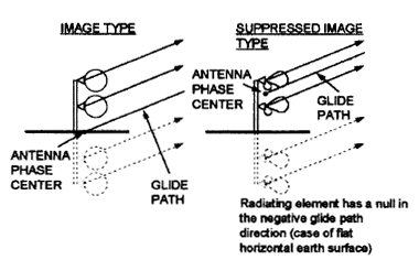
ILS Suppressed Image Antennas, Figure 2.
The most common glide slope antenna reflects an image of its signal off the surface in front of the antenna to create the mirror image of the signal. A more expensive antenna does this electronically and is therefore easier to site. The former can be thrown off by surface snow and the latter by snow in front of the antenna.
Source: ILS Suppressed Image Antennas, page 253.
I've heard that in either case the beam is deflected upward so you won't be closer to the ground but your descent rate might be more than you bargained for. The airport should have test data to indicate when the glide slope is bent beyond category limits and should NOTAM the glideslope and prohibit descent below localizer minimums. At KBED, for example, 18 to 24 inches of snow in front of the glide slope antenna can bend the beam beyond 3.1 degrees, the limit for Category D aircraft.
3
Localizer trapezoid
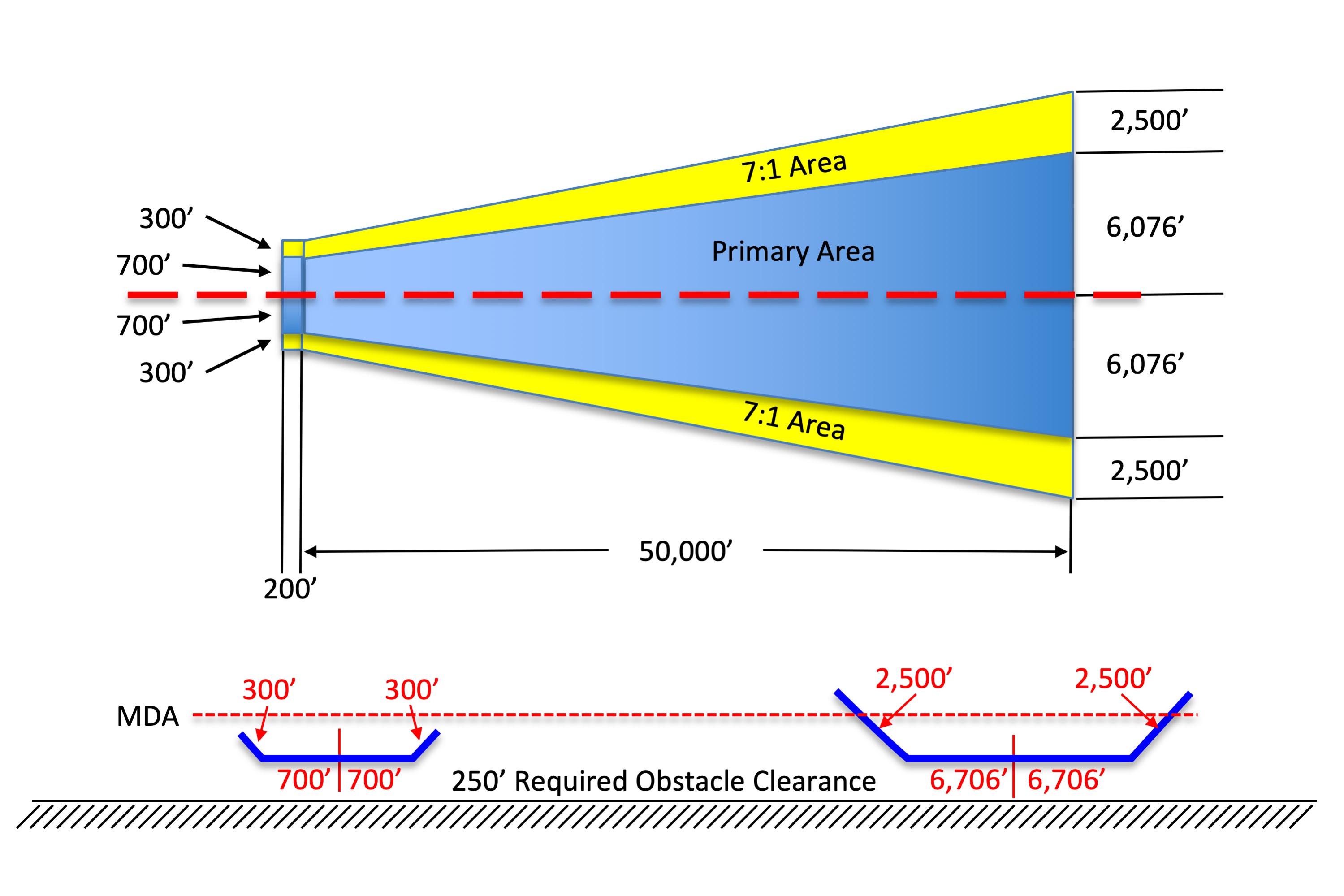
edrawn from TERPS, Vol. 1, Ch. 9, ¶904, figure 75.
The final approach dimensions are specified [in the figure]. . . . Calculate the width of the area using the following formulae:
Perpendicular Width from RCL to the Edge of the Primary = 0.10752 (D - 200) + 700
Perpendicular Width from RCL to the Edge of the Transitional Sfc = 0.15152 (D - 200) + 1000
Where D = Distance (ft) from RWT measure along RCL.
Source: TERPS, Vol. 1, Ch. 9, ¶903
RCL is runway centerline and RWT is runway threshold.
In the example shown, when 50,200' (8.26 nm) from the end of the runway, the primary area extends 6,076' (1 nm) either side of centerline. On a localizer only approach, without a glideslope, the required obstacle clearance (ROC) will be 250' below the MDA. But a glide slope changes everything. . .
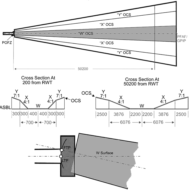
TERPS, Vol. 3, Ch. 3, figure 3-1.
The area originates 200 feet from LTP or FTP and ends at the PFAF/Glide path intercept point (GPIP). The primary area consists of the “W” and “X” OCS, and the secondary area consists of the “Y” OCS. See figure 3-1.
Source: TERPS, Vol. 3, Ch. 3, ¶3.0
TERPS appears to draw the OCS right down to the surface but you have to consider the glide slope. What is important to understand at this point is the lateral dimensions are a bit tighter on the ILS than the localizer-only.
4
Sloping Obstacle Clearance Surface (OCS)

TERPS, Vol. 1, Ch. 2, figure 1-2.
The obstacle evaluation method for descent of a is the application of a descending OCS below the . The vertical distance between the and the OCS is ROC; i.e., ROC = ( height) - (OCS height). The ROC decreases with distance from the final approach fix as the OCS and converge on the approach surface baseline (ASBL) height (see figure 1-2). The OCS slope and angle values are interdependent: OCS Slope = 102 ÷ angle; or angle = 102 ÷ OCS slope. This relationship is the standard that determines the ROC value since ROC = ( height) - (OCS height)
Source: TERPS, Vol. 1, Ch. 2, ¶203.a.

TERPS, Vol. 1, Ch. 2, ¶203.
The OCS formula may look simple but it is made needlessly complex by the Byzantine TERPS practice of "run over rise" slopes, which is opposite of how engineers and pilots think. The slope of a 3° , for example, is found by dividing the run, say 6,076' for a nautical mile, by the height at that point, which would be 318' — so, 3° slope = 6076 ÷ 318 = 19.11 : 1.
| Category | GPA |
| A (80 knots or less) | 6.4 |
| A (81 - 90 knots) | 5.7 |
| B | 4.2 |
| C | 3.6 |
| D & E | 3.1 |
Source: Table 2-2a. Maximum GPA's, from TERPS, Vol. 3, Ch. 2, ¶2.5.
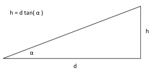
Solve h given d and α
The OCS on a glide path is fairly standard given the distance from the glide path's intercept with the runway and the glide path angle itself. If an obstacle penetrates the OCS, the glide path angle is raised until it doesn't. If the glide path angle then exceeds the maximum for the aircraft category, that category of approach is disallowed.
To find the height of the glide path at any given distance, multiply that distance by the tangent of the glide path angle. For example, a 3° glide path is (6076) tan ( 3° ) = 318' at 1 nm, (5)(6076) tan ( 3° ) = 1592' at 5 nm.
To find the minimum height above obstacle along a glide path, you need to figure the slope of the glide path angle, the slope of the OCS, convert the OCS to an angle, compute the height of each, and subtract. Simple! For example . . .
Given a 3° glide path
Glide path slope is 6076 ÷ 318 = 19.11 : 1.
OCS slope is 102 ÷ ( 3° ) = 34 : 1
OCS angle is arctan ( 1 / 34 ) = 1.68°
Glide path height at any given distance is d tan ( 3 ° )
OCS height at any give distance is d tan ( 1.68° )
ROC at any given distance is the glide path height minus the OCS
For a 3° glide path:
| Distance (nm) | Distance (feet) | Glide path height | OCS height | ROC |
| 1 | 6076 | 318 | 178 | 140 |
| 2 | 12,152 | 637 | 356 | 281 |
| 3 | 18,228 | 955 | 535 | 420 |
| 5 | 30,380 | 1,592 | 891 | 701 |
5
"On course"
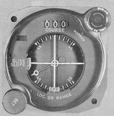
Technical Order 1T-37B-1, figure 4-8.
I flew my first ILS looking at a course indicator and was told I could consider myself on course when the CDI came "off the wall." On a procedure turn, for example, it was okay to descend to the inbound altitude once the CDI was no longer fully deflected. Years later I adopted a "centered or nothing" attitude, thinking I am better than a nearly fully deflected needle. But it begs the question, do we have the required obstacle clearance when the needle just comes off the wall. If not, what about one dot? FAA-H-8083-15B, Instrument Flying Handbook, pg. 7-27, says one-quarter scale deflection means the airplane is aligned with the runway and full scale deflection shows when the aircraft is 2.5° either side of centerline. (The text says 2.5° and the diagram says 1.4°, we'll use 2.5° to take the worst case scenario.) Will we have the required obstacle clearance at full scale deflection?
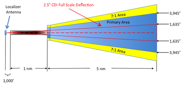
You cannot come up with a one-size fits all rule about where full scale CDI deflection places you because the trapezoid begins 200' before the runway and the angle on the CDI begins at the localizer antenna, on the other side of the runway. We can, however, provide an example. If the runway is 1 nm long (6,076'), and the localizer antenna is 1,000' from the opposite end of that runway, and we check our displacement at 5 nm (30,380'):
- The trapezoid primary area is 0.10752 (30,380 - 200) + 700 = 3,945' either side of centerline
- The 2.5° angle is displaced (30,380' + 6,076 + 1,000) tan (2.5°) = 1,635' either side of centerline
This lends credence to the old conventional wisdom that once you are "off the wall," you are close enough to being on course to call it on course. What about the tighter lateral dimensions of the ILS on the obstacle clearance surface? The TERPS example is for 50,200' so using the same methodology:
- The trapezoid secondary area ("X" plus "W" shown above) is 6,076' either side of centerline
- The trapezoid primary area ("W" shown above) is 2,200' either side of centerline
- The 2.5° angle is displaced (50,200' + 6,076 + 1,000) tan (2.5°) = 2,500' either side of centerline
The needle comes "off the wall" about 300' too early, but that is based on being right on the obstacle clearance surface. Drawing the slope of the secondary area (4:1) you could argue that you are still covered 2,500' either side of centerline as long as your intercept takes place at least 1,200' above the OCS (the 4:1 that gets you the extra 300' of lateral displacement). But when flying the intercept how are you going to know exactly where that OCS is? You won't. But it doesn't matter for those of us who also fly outside the United States. . .
5.5.5.1 The width of the ILS/MLS/GBAS final approach protection area is much narrower than those of non-precision approaches. Descent on the glide path/MLS elevation angle must never be initiated until the aircraft is within the tracking tolerance of the localizer/azimuth.
5.5.5.2 The protection area assumes that the pilot does not normally deviate from the centre line more than half-scale deflection after being established on track. Thereafter the aircraft should adhere to the on-course, on-glide path/elevation angle position since a more than half course sector deflection or a more than half course fly-up deflection combined with other allowable system tolerances could place the aircraft in the vicinity of the edge or bottom of the protected airspace where loss of protection from obstacles can occur.
Source: ICAO Doc 8168, Vol 1, §4, Chapter 5, ¶5.5.5.
Conclusion: You might have the required obstacle clearance when descending on an ILS glide path as long as the CDI is just "off the wall," but the ICAO wants you within a half-scale deflection. Using a half-scale deflection also removes all uncertainty from the TERPS secondary area as well.
6
Good enough?
If the ICAO says half-scale deflection is "on course," how much deflection is good enough over the runway to assume you are over the runway?
This is hard to answer because not all localizers and localizer displays are the same. But we can make a few generalizations to come up with a generalized answer.
An ILS localizer antenna is normally found some distance beyond the departure end of the runway. Let's say we have a 7,000' runway and the antenna is another 1,000' beyond that. Let's also say we want to land in the touchdown zone, which is 1,000' beyond the approach end, making our distance to the localizer antenna 7,000'. Now let's say our aim is to land within 50' of centerline. How many degrees from centerline is that?
A typical localizer display may have full scale deflection of 2.5° so you are going to have to get wtihin 0.4 / 2.5 = 0.16 of full scale deflection, between one-tenth and one-fifth scale deflection. So just because the ICAO says half-scale deflection is "on course," doesn't mean you can actually land the airplane with that tolerance.
References
(Source material)
Air Force Manual (AFM) 51-37, Instrument Flying, 1 December 1976
FAA-H-8083-15B, Instrument Flying Handbook, U.S. Department of Transportation, Flight Standards Service, 2012
ICAO Doc 8168 - Aircraft Operations - Vol I - Flight Procedures, Procedures for Air Navigation Services, International Civil Aviation Organization, 2006
Lopez, Alfred. Suppressed-Image ILS Glide Slope Antenna, ARL Associates Incorporated, Proceedings of the 51st Annual Meeting of the Institute of Navigation, Colorado Springs, CO, June 1995, pp. 253-259.
Technical Order 1T-37B-1, T-37B Flight Manual, USAF Series, 30 September 1959
United States Standard for Terminal Instrument Procedures (TERPS), Federal Aviation Administration 8260.3B CHG 26, 02/24/2014