The twin-spool, axial flow, computer controlled, high-bypass ratio, fan jet engine is a marvelous creation. Right around 1970 it was truly perfected with the advent of the General Electric CF-6. But, if like me, you were brought up on a lesser jet, you may have had a few failures and fires along the way. Now that they've become so much more reliable, we tend to take them for granted. We may not fully realize why the engine behaves as it does. Engine spool-up time can be life threatening if not understood. (See the case of: Gulfstream G550 N535GA.) Thrust measurement isn't as straight forward as you might think and the proportion of thrust to power level angle isn't linear.
— James Albright

Updated:
2015-04-15
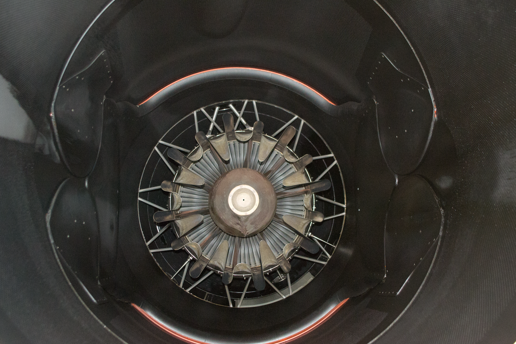
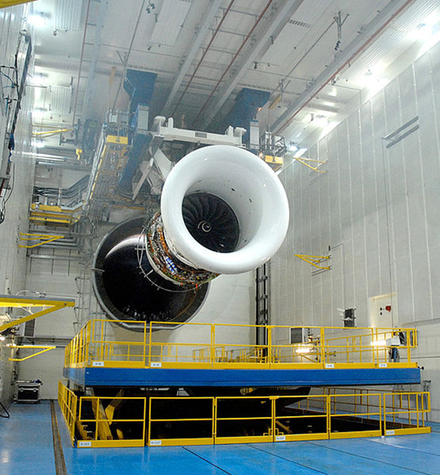
A view of a G450's engine
(from the tailpipe)
Do you need to know this to fly a jet airplane? No. But knowing more than just "push means fast, pulls means slow" will help you operate more efficiently and to diagnose what ails your engines should that time ever come.
2 — A comparison of jet engine types

1
Principles of propulsion
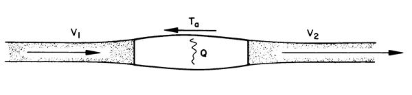
Principles of propulsion, from Hurt, figure 2.5.
- You can summarize how a jet engine works with two of Newton's Laws of Motion. Newton's second law can be written as:
- A force F acting on a mass will cause the mass to accelerate in the direction of the force. The mass is air passing through the jet engine.
- Newton's third law of motion states that for every action force there is an equal and opposite reaction force. The action force is the air mixture accelerating aft, the reaction force is on the engine itself, accelerating forward.
F = ma
Source: ATCM 51-3, Pg. 105
But what does that really mean? The mass being accelerated aft is fuel and air mixture. The mass is pushing against various components of the engine which in turn push the engine (and therefore the airplane) forward. On some aircraft, like the early KC-135A, water is added to the fuel air mixture to increase the mass being accelerated.
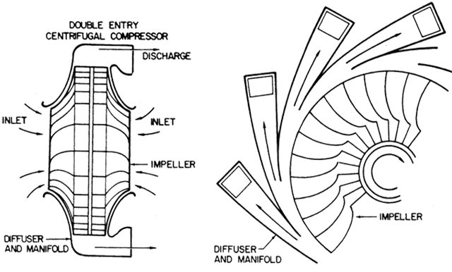
Centrifugal compressor, from Hurt, figure 2.7 (top).
- The compressor must furnish the combustion chamber with large quantities of high pressure air in a most efficient manner. Since the compressor of a jet engine has no direct cooling, the compression process takes place with a minimum of heat loss of the compressed air.
- The centrifugal flow compressor has great utility, simplicity, and flexibility of operation. The operation of the centrifugal compressor requires relatively low inlet velocities and a plenum chamber or expansion space must be provided for the inlet. The single stage centrifugal compressor is capable of producing pressure ratios of about three or four with reasonable efficiency.
Source: Hurt, pg. 109
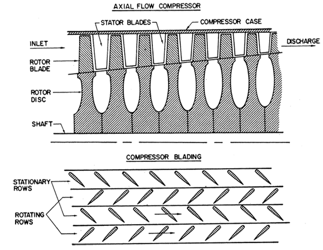
Axial compressor, from Hurt, figure 2.7 (bottom)
- The axial flow compressor consists of alternate rows of rotating and stationary airfoils.
- A pressure rise occurs through the row of rotating blades since the airfoils cause a decrease in velocity relative to the blades. Additional pressure rise takes place through the row of stationary blades since these airfoils cause a decrease in the absolute velocity of the flow.
- While the pressure rise per stage of the axial compressor is relatively low, the efficiency is very high and high pressure ratios can be obtained efficiently by successive axial stages. The multistage axial flow compressor is capable of providing pressure from five to ten (or greater) with efficiencies which cannot be approached with a multistage centrifugal compressor.
Source: Hurt, pg. 111
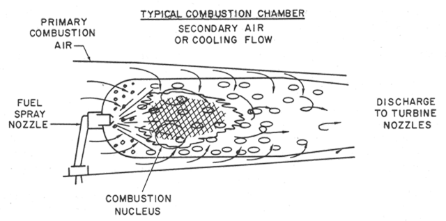
Combustion chamber, from Hurt, figure 2.8 (top)
- The combustion chamber must convert the fuel chemical energy into heat energy and cause a large increase in the total energy of the engine airflow. The combustion chamber will operate with one principal limitation: the discharge from the combustion chamber must be at temperatures which can be tolerated by the turbine section.
- The combustion chamber receives the high pressure discharge from the compressor and introduces approximately one half of this air into the immediate area of the fuel spray.
- The fuel nozzle must provide a finely atomized, evenly distributed spray of fuel through a wide range of flow rates.
- The temperatures in the combustion chamber nucleus can exceed 1,700° to 1,800°C but the secondary air will dilute the gas and reduce the temperature to some value which can be tolerated in the turbine section.
Source: Hurt, pg. 111
The typical introductory text might leave you to believe this is where thrust comes from: the gas explodes aft, pushing the combustion chamber forward. But most burner cans are hardly the robust structures that can withstand this amount of force. There is something else in play here . . .
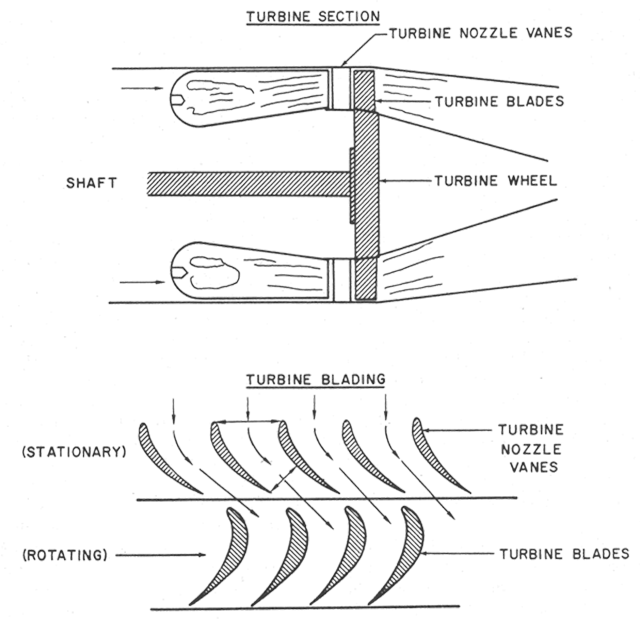
Turbine section, from Hurt, figure 2.8 (bottom)
- The turbine section is the most critical element of the turbojet engine. The function of the turbine is to extract energy from the combustion gases and furnish power to drive the compressor and accessories. In the case of a turboprop engine, the turbine section must extract a very large portion of the exhaust gas energy to drive the propeller in addition to the compressor and accessories.
- The turbine nozzles vanes are a row of stationary blades immediately ahead of the rotating turbine. These blades form the nozzles which discharge the combustion gases as high velocity jets onto the rotating turbine. In this manner, the high pressure energy is converted into kinetic energy and a pressure and temperature drop takes place. The function of the turbine blades operating in these jets is to develop a tangential force along the turbine wheel thus extracting mechanical energy from the combustion of gases.
Source: Hurt, pg. 113
The rotating turbine blades are where all the heat and pressure are converted into the mechanical energy used to rotate the forward fan (or propeller), run the accessories, and most importantly to push the center shaft forward. This is where thrust gets transmitted to the airplane and this is another reason the bearings holding that shaft in place are so critical.
2
A comparison of jet engine types
Centrifugal Compressor Engine
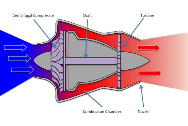
Centrifugal compressor engine
A centrifugal compressor uses a series of blades mounted on a disk to throw incoming air outboard to a cylindrical shaft which funnels the air aft. The air is thus compressed and made ready for combustion. A centrifugal compressor is relatively cheap to make because the required tolerances between moving parts are not as critical as with an axial flow compressor. The centrifugal compressor, however, is not capable of the high compression rates needed to produce very high levels of thrust. The centrifugal compressor engine as a relatively large front area, increasing parasite drag. The thrust to weight ratio of a centrifugal compressor is much lower than of an axial flow compressor.
Example: The T-37 has two centrifugal compressor engines. Many modern auxiliary power units also use centrifugal compressor engines.
Axial Flow Engine
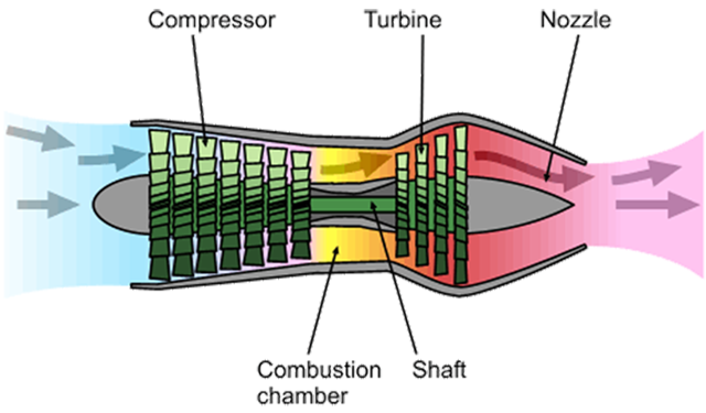
Axial flow engine, from Emoscopes (Creative Commons)
An axial compressor produces much higher pressure than a centrifugal compressor and therefore makes much higher thrust possible at much higher efficiencies. (You get more thrust for less fuel.) Single-spool axial compressor engines do require complicated blade angle control systems to achieve higher pressure ratios, complicating the design and reducing reliability.
Example: The T-38 has two axial flow engines.
Twin spool Compressor Engine
Twin spool engine, from K. Aainsqatsi (Creative Commons)
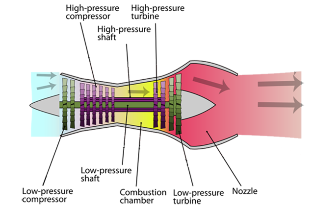
A twin spool design normally has the front compressors attached to the rear turbines using an inner shaft, with a higher pressure compressor and a higher pressure turbine connected with an outer shaft. Since the shafts are free to rotate independently, the engine can be designed for even higher compression without the need for complicated automatic blade control systems.
Example: The KC-135A has four twin-spool engines engines.
Fan Bypass Engine
Fan bypass compressor engine, from K. Aainsqatsi (Creative Commons)
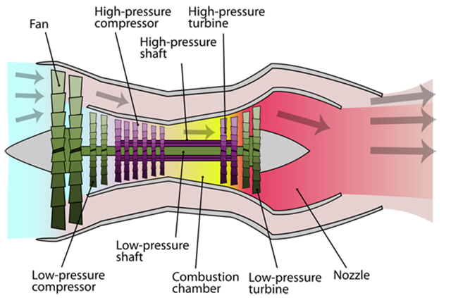
A fan bypass engine takes some of the compressor or fan air outside of the engine core to bypass the combustion section. The mixing of colder and lower speed air with the hotter and higher speed exhaust allows for higher turbine temperatures and thrust while also serving to lower the noise level of the engine.
Example: The G450 has two fan bypass engines.
High Bypass Fan Engine
Bypass fan compressor engine, from K. Aainsqatsi (Creative Commons)
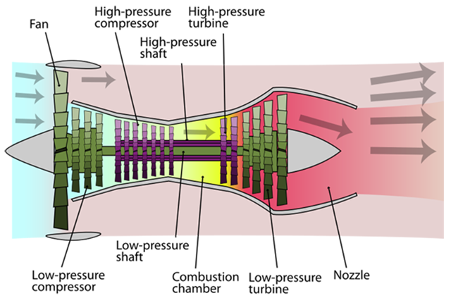
A high bypass fan engine normally includes a large first fan surrounded by a separate duct, allowing a majority of the fan air to bypass the engine. The fan acts much like a propeller in a turboprop, without the problems of propeller slipstream and drag.
Example: The Boeing 747 has four high bypass fan engines.
3
Engine spool-up time
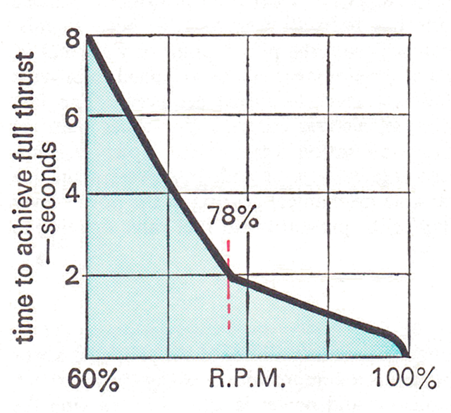
Engine acceleration times, from Davies, figure 4.11
- In a propeller installation the constant speeding ability of the propeller keeps the engine turning at an r.p.m. which is a compromise between the approach and baulked landing power conditions and power is altered by varying the boost pressure. To increase power quickly the boost is increased, the propeller coarsens off and the demanded thrust is supplied quickly. 'Quickly' in this context means about 3 to 4 seconds because of the propeller momentary overspeed tendency which is not acceptable to a pilot with any sympathy for mechanical engineering devices.
- Efficiency in a jet engine is highest at high r.p.m. where the compressor is working closest to its optimum conditions of gas flow, etc. At low r.p.m. the operating cycle is generally inefficient. If a sudden demand is made for more thrust from an r.p.m. equivalent to a normal approach r.p.m. the engine will respond immediately and full thrust can be achieved in about 2 secs. From a lower r.p.m., however, a sudden demand for maximum thrust will tend to overfuel the engine and cause it to overheat or surge. To prevent this various limiters are contained in the fuel control unit and these serve to restrict the engine until it is at an r.p.m. at which it can respond to a rapid acceleration without distress. This critical r.p.m. is most noticeable when doing a slam acceleration from an idle thrust setting. Acceleration is initially very slow indeed but then changes to very quick as r.p.m. rises through this significant value. From idle thrust to substantially full thrust at a typical approach speed takes about 6 secs. on average. Some engines are better than others, but there is also a scatter between individual engines of the same type; so occasionally the full 8 secs. permitted by the requirements is needed.
Source: Davies, page 59.
There have been two contrary trends in jet engine design when it comes to spool-up time. Full Authority Digital Engine Control (FADEC) should give you all the power you need as quickly as the engine can tolerate it. But the sheer size of modern engines makes it harder to accelerate from lower speeds just due to the centrifugal mass of the fans and compressors. It has been my experience that the larger the engine, the longer to spool-up time from low RPMs.
This slow spool-up tendency from lower RPMs can have adverse affects on a pilot not ready for it. In a G450, for example, if the flaps are set to less than 22° the engines will not go into "high idle" mode, significantly increasing engine spool-up time.
More about this: G450 Powerplant / Idle Thrust Management.
4
Jet engine thrust measurement
Rolls-Royce turbofan engine test facility, Derby, UK, from Cherry Salvesen (Creative Commons)
Test Stand Measurement
Jet engines are commonly rated in terms of static thrust. The engine is restrained from moving and the "push" is measured with scales. In actual use, the true thrust is normally less than static thrust, since exhaust pressure tends to be constant and input pressure increases with aircraft velocity, so the acceleration goes down. There are no scales to measure this.
Engineering Solution
We can measure drag in a wind tunnel and when the aircraft is in steady flight we know thrust equals drag and can therefore be approximated.
Engine RPM
Engine thrust can also be approximated by the engine's number of revolutions per minute, RPM. These numbers are converted to a percentage of a rated value for ease of reading. For twin spool engines, the inner spool is often connected to the most forward and aft sections and is called N1, the outer spool is called N2. Thrust normally does not vary in a linear relationship with RPM. In a typical engine thrust can be idle around 50%, a quarter of maximum at 90%, half at 95%, and maximum at 100%.
Engine Pressure Ratio
A common method of presenting the pilot with an approximation of engine thrust is EPR, engine pressure ratio. In its basic form, pressure probes are positioned at the inlet and outlet, the outlet pressure is divided by the inlet to determine EPR. This number is not an accurate representation of thrust because the pressure pattern of the exhaust tends to be higher in the center and lower in the outer portions of the airflow. It is, however, good enough since it gives the pilot a way of telling relative power settings from idle to maximum.
Later engines use ambient air pressure instead of air inlet pressure, since it is close enough. Many engines do not measure outlet pressure because the temperatures tend to shorten the lives of probes. Instead these engines choose intermediate stages of pressure, such as aft of the compressor. EPR, then, has very little to do with pressure ratios and is nothing more than a fictitious number designed to give pilots an idea of relative thrust levels.
Regardless of how you measure thrust it is important to realize the metric you are using in the cockpit does not correlate one-to-one with thrust. . .
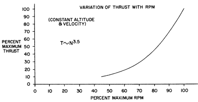
Variation of thrust with rpm, from Hurt, figure 2.10 (middle)
The variation of thrust output with engine speed is a factor of great importance in the operation of a turbojet engine. By reasoning that static pressure changes depend on the square of the flow velocity, the changes of pressure throughout the turbojet engine would be expected to vary as the square of the rotative speed, N. However, since a variation in rotative speed will alter airflow, fuel flow, compressor and turbine efficiency, etc., the thrust variation will be much greater than just the second power of rotative speed. Instead of thrust being proportional to N2, the typical fixed geometry engine develops thrust approximately proportional to N3.5. The turbojet engine usually has a strong preference for high RPM to produce low specific fuel consumption.
Source: Hurt, pg. 117
5
Power level angle
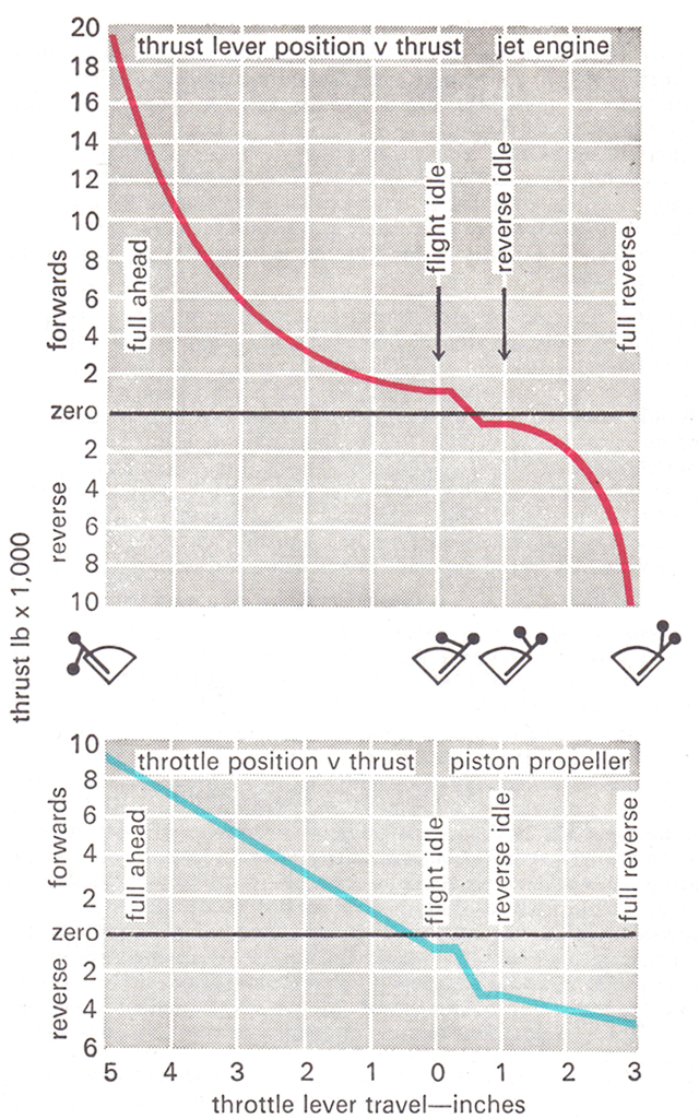
Relationship between power lever position and thrust, from Davies, figure 4.10.
Handling the Big Jets was written in 1967 and remains my favorite text on how to fly airplanes. But a lot has happened since then. If you are not flying an airplane with a Fully Automatic Digital Engine Control (FADEC), then all that follows probably applies to you. If you are flying a FADEC-equipped airplane, it might apply to you. I can show you how it works on a G450, below. You will have to research your aircraft to be sure.
[The figure] shows quite simply thrust lever position against thrust, from full ahead to full astern, for both a piston propeller installation and a pure jet installation. These diagrams do not represent particular installations and the characteristics have been deliberately exaggerated in order to accentuate the differences. The following facts are all important in terms of flight handling qualities:
- Thrust is more or less proportional to throttle position in a propeller installation (note the straight line), but quite disproportional in a jet (note the curve steepening sharply at high r.p.m.). An inch of throttle movement is worth say 700 horse power wherever the throttle might be. On a jet, an inch of thrust lever movement at low r.p.m. might be worth only 500 lb. thrust, but at high r.p.m. will be worth more like 5,000 lb. of thrust. This is why, if significantly more power is needed from a low thrust lever setting, it is no good inching the lever up a bit — if the power is needed, give it a handful. This doesn't mean to say that it is necessary to be rough with the levers at all times; if they are at a typical approach power setting then only small changes need be made.
- Throttle closed on a propeller installation produces drag — not the continuance of the thrust line to below zero in the forward range. Thrust lever at idle on a jet leaves some forward thrust on — notice there is about 1,000 lb. of forward thrust at flight idle.
- The net change in thrust between forward idle and reverse idle on a propeller is very large — notice the steepness of the line. As the propeller reverses the drag, really builds up and at reverse idle the propeller is already producing about 60% of its maximum possible drat at full power — the remainder being achieved by opening up in reverse. On a jet engine, however, the net change in thrust between forward idle and reverse idle is very small; with a reverser efficiency of 50% the net change will be from 1,000 lb. forwards to 500 lb. reverse.
Source: Davies, page 57.
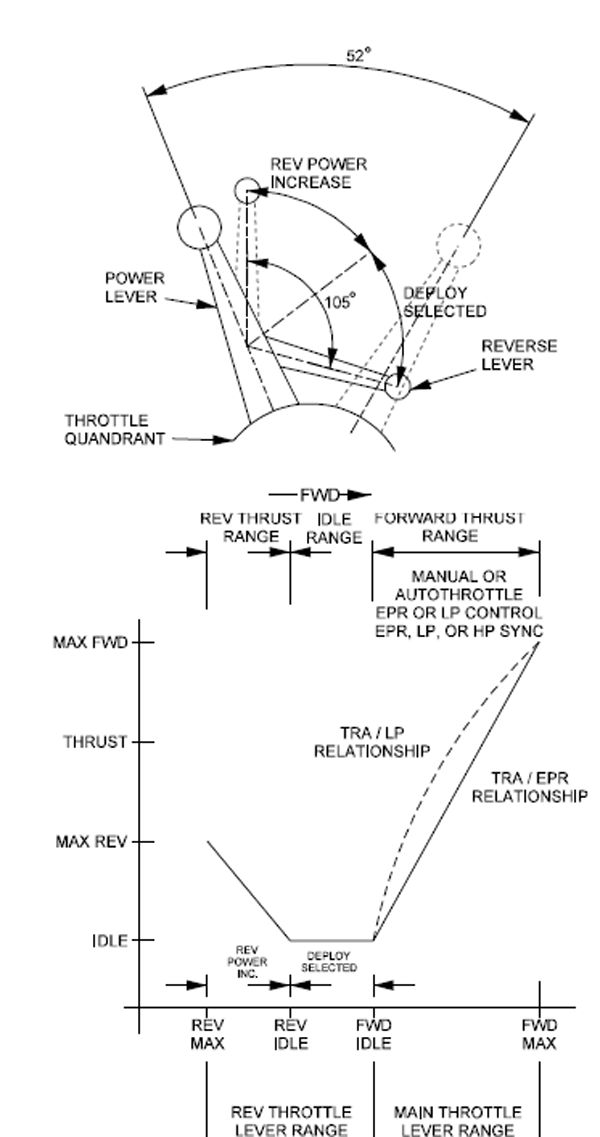
G450 Aircraft Operating Manual, §2A-76-30 ¶1.
This mismatch between power lever angle and actual thrust grew from the limitations of mechanical fuel controls and the inherently nonlinear relationship of thrust to RPM. Modern aircraft can easily fix this with computerized engine control. In the case of a G450, the "Throttle Resolver Angle" is linear to EPR and skewed toward the middle in relation to RPM.
References
(Source material)
Air Training Command Manual 51-3, Aerodynamics for Pilots, 15 November 1963
Davies, D. P., Handling the Big Jets, Civil Aviation Authority, Kingsway, London, 1985.
Gulfstream G450 Aircraft Operating Manual, Revision 35, April 30, 2013.
Hurt, H. H., Jr., Aerodynamics for Naval Aviators, Skyhorse Publishing, Inc., New York NY, 2012.
Please note: Gulfstream Aerospace Corporation has no affiliation or connection whatsoever with this website, and Gulfstream does not review, endorse, or approve any of the content included on the site. As a result, Gulfstream is not responsible or liable for your use of any materials or information obtained from this site.