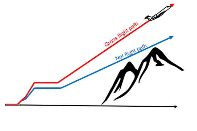
If your aircraft was manufactured under the auspices of 14 CFR 25, which means just about everyone, then the foundation of your ability to takeoff without hitting anything is captured by the diagram here. The critical thing to understand is that the airplane, with you at the controls, will fly the orange line. The "gross flight path" is nothing more than what the airplane will do with an engine failed if flown according to the airplane flight manual. The blue line, the "net flight path," is an arbitrary reduction of a specified amount. Your flight manual performance data is all net data. What does that mean to you? It means you and your aircraft will outperform your flight manual.
— James Albright

Updated:
2017-01-19
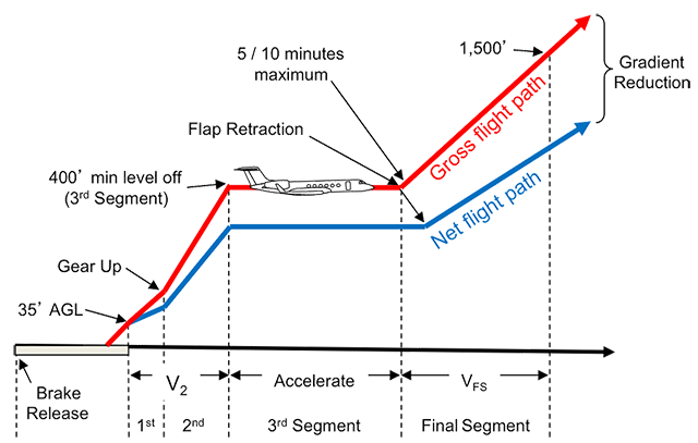
Takeoff segments
This section walks you through the construction of this graph, attempting to show exactly what goes behind each number and the decisions you as a pilot make along the way. None of this is rocket science, but it is amazing how misunderstood it can be. I still hear in various forums that gross is "test pilot" and net is "average pilot." Not true.
There are those who say the net flight path is unnecessary and can easily be subtracted from climb performance numbers as a way on increasing aircraft departure payloads. I think that is a foolish strategy if you happen to run into a tailwind at altitude or temperature inversion. There are, however, other margins that can help you out. See: Departure Obstacle Avoidance Strategy.

1
Gross flight path
Takeoff Run
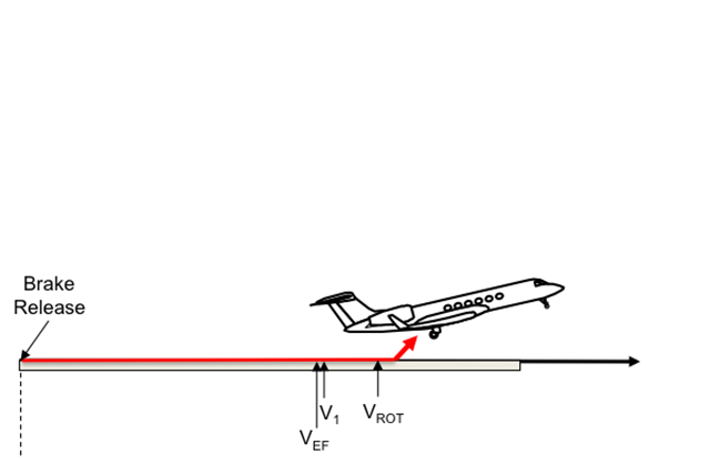
Takeoff / Engine Failure / Rotate,
The takeoff path extends from a standing start to a point in the takeoff at which the airplane is 1,500 feet above the takeoff surface, or at which the transition from the takeoff to the en route configuration is completed and VFTO is reached, whichever point is higher.
Source: 14 CFR 25, §25.111
Other than to say it is a "standing start," 14 CFR 25 leaves the method of getting the airplane onto the runway up to the manufacturer but it is nonetheless important. The more runway you use getting the aircraft to takeoff power, the closer to the obstacle you will be. If you have a close-in obstacle you should be mindful of that procedure. Here is how it is done in the G450:
Field length limited takeoff performance presented in this Airplane Flight Manual is based on a non-rolling takeoff. The following takeoff procedure was assumed for the determination of takeoff performance provided and should be used in actual takeoffs:
- Line up on runway
- Brakes on, ground spoilers armed, and flaps at 10° or 20°
- Advance power to takeoff setting
- When takeoff thrust has been established, release brakes
Source: G450 Airplane Flight Manual, §5.2
The airplane must be accelerated on the ground to VEF, at which point the critical engine must be made inoperative and remain inoperative for the rest of the takeoff; and
(3) After reaching VEF, the airplane must be accelerated to V2.
(b) During the acceleration to speed V2, the nose gear may be raised off the ground at a speed not less than VR. However, landing gear retraction may not be begun until the airplane is airborne.
Source: 14 CFR 25, §25.111
(a) V1 must be established in relation to VEF as follows:
(1) VEF is the calibrated airspeed at which the critical engine is assumed to fail. VEF must be selected by the applicant, but may not be less than VMCG determined under §25.149(e).
(2) V1, in terms of calibrated airspeed, is selected by the applicant; however, V1 may not be less than VEF plus the speed gained with critical engine inoperative during the time interval between the instant at which the critical engine is failed, and the instant at which the pilot recognizes and reacts to the engine failure, as indicated by the pilot's initiation of the first action (e.g., applying brakes, reducing thrust, deploying speed brakes) to stop the airplane during accelerate-stop tests.
Source: 14 CFR 25, §25.107
We often think of V1 as "decision speed" but this is not true. The decision must have been made by V1. More about this: V1. The engine failure is considered to have taken place at VEF, followed by a pilot's decision and then action. When does the action happen? It depends on aircraft manufacturer. In the case of the G450 the pilot is given 1.0 seconds:
TAKEOFF DECISION SPEED - the speed from which a decision to continue the takeoff results in a takeoff distance that will not exceed the available accelerate-go distance, or from which a decision and action to bring the airplane to a full stop will not exceed the accelerate-stop distance available. In the event of an engine failure, this speed takes account of the pilot recognition and reaction time of 1.0 seconds, including the pilot's first action after recognizing the engine failure. For an all-engine rejected takeoff, this is the speed at which the pilot performs his first action to abort.
Source: G450 AFM §5.1-3
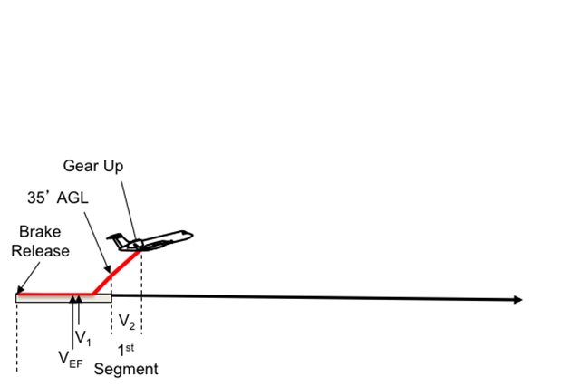
First Segment
First Segment
Takeoff path.
(a)(3) After reaching VEF, the airplane must be accelerated to V2.
(b) During the acceleration to speed V2, the nose gear may be raised off the ground at a speed not less than VR. However, landing gear retraction may not be begun until the airplane is airborne.
(c) During the takeoff path determination in accordance with paragraphs (a) and (b) of this section—
(1) The slope of the airborne part of the takeoff path must be positive at each point;
(2) The airplane must reach V2 before it is 35 feet above the takeoff surface and must continue at a speed as close as practical to, but not less than V2, until it is 400 feet above the takeoff surface;
Source: 14 CFR 25, §25.111
Note: You cannot descend while accelerating to V2.
There is nothing official about the terms "first segment," "second segment," and so forth. But the terminology is in wide use so we'll adopt it here. The takeoff run ends and the first segment begins as the aircraft passes 35 feet above the runway. The airplane is not allowed to descend at any time while making it to this point and is expected to achieve V2 by 35 feet.
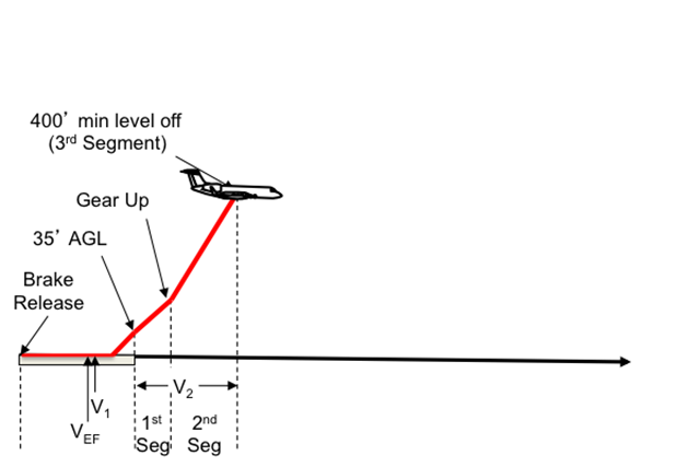
Second Segment to 400'
Second Segment
Takeoff; landing gear retracted. In the takeoff configuration existing at the point of the flight path at which the landing gear is fully retracted, and in the configuration used in §25.111 but without ground effect:
(1) The steady gradient of climb may not be less than 2.4 percent for two-engine airplanes, 2.7 percent for three-engine airplanes, and 3.0 percent for four-engine airplanes, at V2 with:
(i) The critical engine inoperative, the remaining engines at the takeoff power or thrust available at the time the landing gear is fully retracted, determined under §25.111, unless there is a more critical power operating condition existing later along the flight path but before the point where the airplane reaches a height of 400 feet above the takeoff surface; and
(ii) The weight equal to the weight existing when the airplane's landing gear is fully retracted, determined under §25.111.
Source: 14 CFR 25, §25.121(b)
Once you've retracted the landing gear you are expected to climb at at least 400 feet, and you have to do this at the minimum rates shown.
Third Segment Acceleration / Clean Up
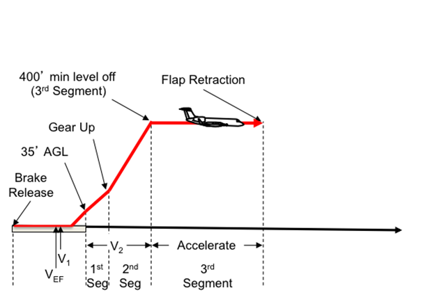
Third Segment
At 400 feet you have the option of cutting your climb rate while accelerating to "the en route configuration" and VFTO.
Final Segment
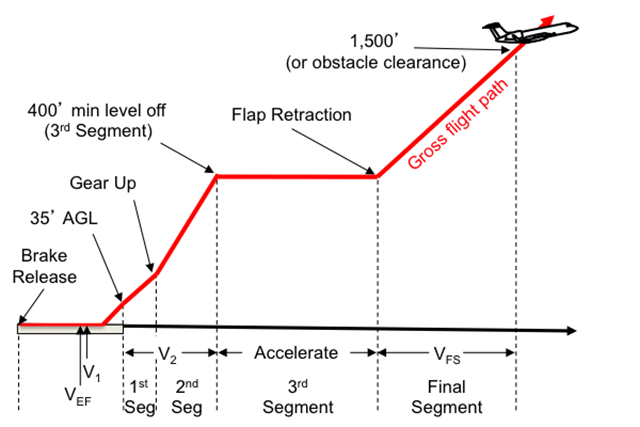
Gross flight path at 1500'
Final takeoff. In the en route configuration at the end of the takeoff path determined in accordance with §25.111:
(1) The steady gradient of climb may not be less than 1.2 percent for two-engine airplanes, 1.5 percent for three-engine airplanes, and 1.7 percent for four-engine airplanes, at VFTO with—
(i) The critical engine inoperative and the remaining engines at the available maximum continuous power or thrust; and
(ii) The weight equal to the weight existing at the end of the takeoff path, determined under §25.111.
Source: 14 CFR 25, §25.121(c)
If you cleaned up to "the en route configuration" and accelerated to VFTO, you must climb at least at the rates shown until 1,500' above the runway or your obstacle clearance height.
Second as Final Segment Option
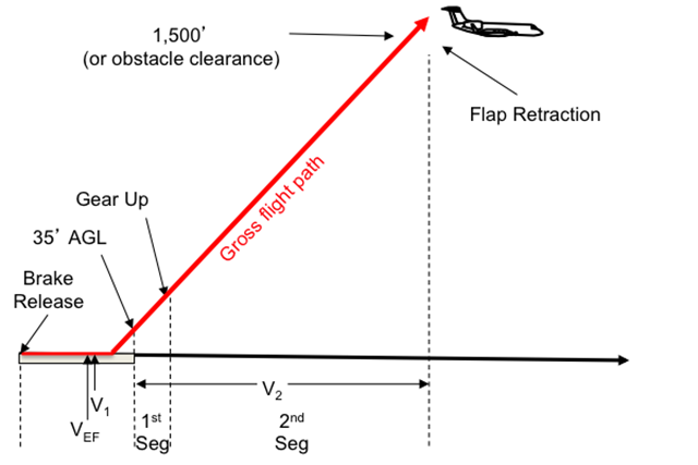
Second Segment as Final Segment
Some aircraft cannot make distant obstacle clearance requirements without retracting flaps; they will need to cut their second segment climb rate at some point to push the nose over and accelerate. They then complete their climbs in the "final segment" flying at VFTO.
What about airplanes with sufficient power to make their second segment climb requirements with flaps extended all the way to 1,500 feet or obstacle clearance height? These airplanes have the option of completely bypassing the third and final segments. The G450, for example, uses second segment climb configuration and speed all the way to obstacle clearance height.
2
Net flight path
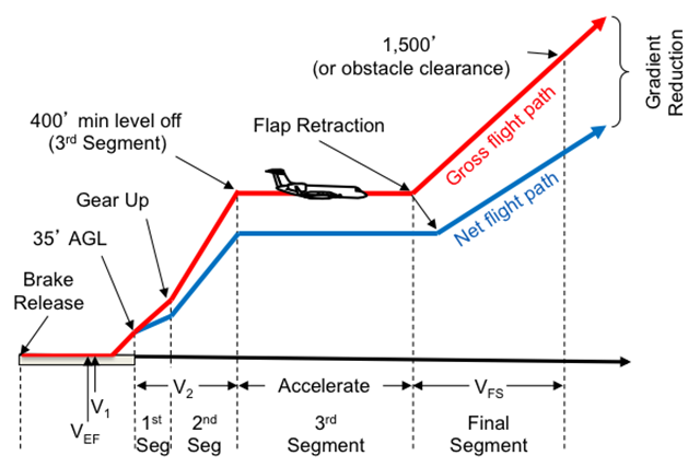
Net Reduction
The term "net" doesn't really exist in the regulation, other than to say it is the actual takeoff flight path minus a factor.
The net takeoff flight path data must be determined so that they represent the actual takeoff flight paths (determined in accordance with §25.111 and with paragraph (a) of this section) reduced at each point by a gradient of climb equal to—
(1) 0.8 percent for two-engine airplanes;
(2) 0.9 percent for three-engine airplanes; and
(3) 1.0 percent for four-engine airplanes.
(c) The prescribed reduction in climb gradient may be applied as an equivalent reduction in acceleration along that part of the takeoff flight path at which the airplane is accelerated in level flight.
Source: 14 CFR 25, §25.115(b)
Aircraft manufacturers must reduce takeoff performance numbers by these amounts and all data in your airplane performance manual reflect these reductions.
3
Obstacle considerations
Takeoff performance over an obstacle
(d) No person operating a turbine engine powered large transport category airplane may take off that airplane at a weight greater than that listed in the Airplane Flight Manual—
(2) For an airplane certificated after September 30, 1958 (SR422A, 422B), that allows a net takeoff flight path that clears all obstacles either by a height of at least 35 feet vertically, or by at least 200 feet horizontally within the airport boundaries and by at least 300 feet horizontally after passing the boundaries.
Source: 14 CFR 135, §135.379
You must plan your takeoff to clear any obstacle within 300 feet horizontally by at least 35 feet under 14 CFR 121 and 135, or just clear the obstacle under 14 CFR 91. But the data you use to make this computation must come from your airplane flight manual and that data has been reduced as shown above.
The difference comes to (0.008)(6076) = 48.6 ft per nautical mile in a two-engine aircraft. For example, let's say you have an obstacle that is 2,000 feet higher than the runway, 10 nm from the departure end of the runway, If your flight manual says you will just clear it with the minimum 35 feet required by 14 CFR 135. The airplane will actually be 2,000 + 10 (48.6) + 35 = 2,521 feet above the runway elevation, or 521 feet above the obstacle.
References
(Source material)
14 CFR 25, Title 14: Aeronautics and Space, Airworthiness Standards: Transport Category Airplanes, Federal Aviation Administration, Department of Transportation
14 CFR 135, Title 14: Aeronautics and Space, Operating Requirements: Commuter and On Demand Operations and Rules Governing Persons on Board Such Aircraft, Federal Aviation Administration, Department of Transportation
Advisory Circular 120-91, Airport Obstacle Analysis, 5/5/06, U.S. Department of Transportation
Gulfstream G450 Airplane Flight Manual, Revision 35, April 18, 2013
United States Standard for Terminal Instrument Procedures (TERPS), Federal Aviation Administration 8260.3B CHG 25, 03/09/2012
Please note: I've used some Gulfstream performance charts for the purposes of education. Gulfstream Aerospace Corporation has no affiliation or connection whatsoever with this website, and Gulfstream does not review, endorse, or approve any of the content included on the site. As a result, Gulfstream is not responsible or liable for your use of any materials or information obtained from this site.