When departing from a domestic to an oceanic area, pilots will have a few extra steps prior to and during the oceanic crossing. While procedures worldwide have become much more standardized, there are differences in various regions. The basic procedures are covered here, with regional differences noted. Of course these procedures are changing every day and you should check prior to every trip.
— James Albright

Updated:
2020-12-23
This section continues an example G450 trip from Bedford, Massachusetts (KBED) to Geneva, Switzerland (LSGG), to Tokyo, Japan (RJAA), back to Bedford. For the purpose of covering an oceanic departure, this section will focus on the KBED to LSGG leg.
4 — FMS flight plan versus filed flight plan
5 — Filed flight plan verification

1
Master document
A clear delineation of preflight tasks can ensure all duties are accomplished in a timely manner and a good level of crosscheck exists between pilots. A possible technique is to have the PIC accomplish all plotting and master document work while the SIC completes the aircraft exterior inspection. Once the interior inspection begins, the PF programs the FMS while the PM accomplishes the aircraft interior inspection checklist. Once that is done, the PM checks the FMS entries while the PF turns his or her attention to other airplane related matters.
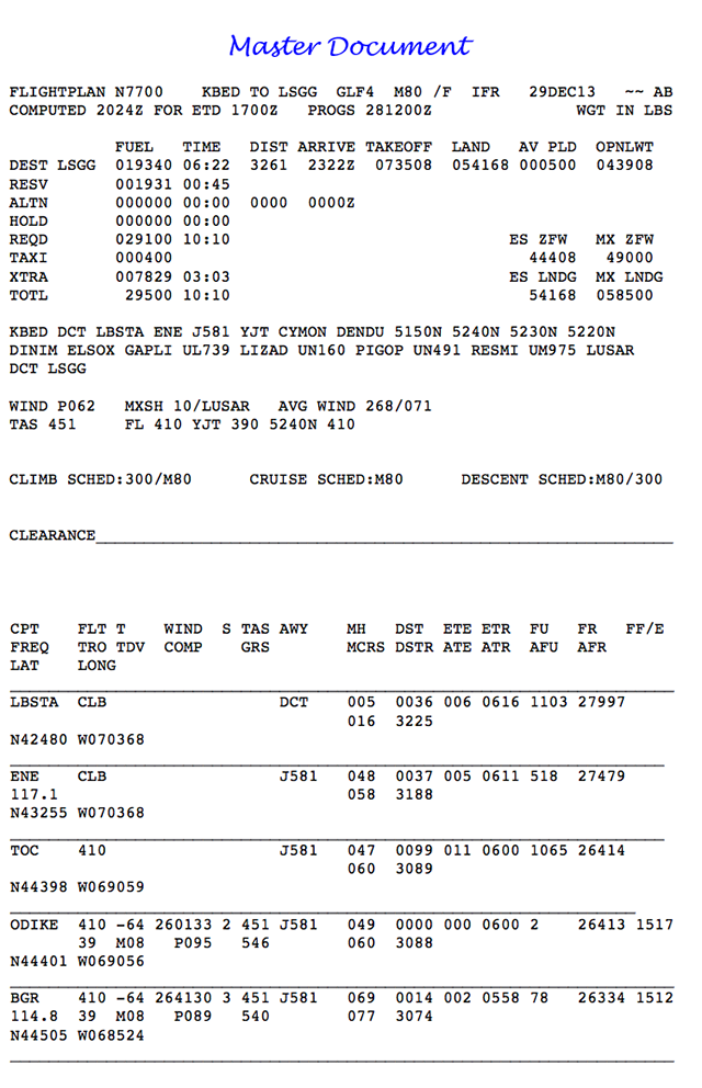
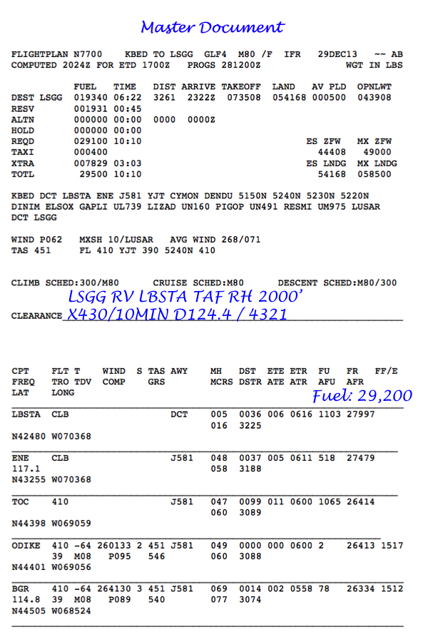
Master flight plan (“master document”). Note: Use strict procedures to manage the master document. Maintain only one copy of the master document in the cockpit.
Source: AC 91-70B, ¶6.3.1.1
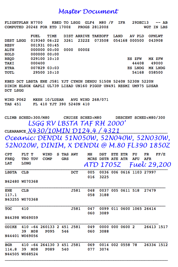
The flight deck can have multiple copies of the electronic flight plan but only one of these can be used as a “master document.” Our example master document includes a cover page, pages on equal time point information, NOTAMS, weather, airport information, and a track message. For the sake of organization, we staple these together and label the cover page “Master Document.” While some crews like to have a copy for each pilot, I discourage the practice to avoid recording required items on the wrong copy. If we have an extra copy, I store it outside the cockpit.
The same discipline should hold when using an electronic master document. It may be possible to link iPads so both pilots can make entries onto the same document in different colors. Otherwise, it should be agreed upon which device has the actual master document and that copy should be labeled accordingly.
Master document example
2
Flight plan entry
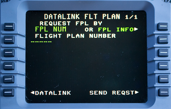
You have several options for getting the flight plan from the Master Document to the FMS, each with its own set of challenges. Among the options:
- Manual entry — If you are diligent and careful, you can get every single point in the flight plan into the FMS. Make sure you don't input any extra points not on the filed flight plan, such as the TOC (Top of Climb) or TOD (Top of Descent). Some flight plans will include FIR boundaries, don't put those in. If the flight plan shows any ETPs (equal time points), leave those out as well. This method risks entry errors due to reading and typing mistakes.
- Disk, Punch Card, or Memory Stick — Some FMS have provision for saving a flight plan to a memory device which can be read by the FMS. While this method eliminates the chance of pilot reading or typing error, it risks the use of the wrong memory device and uploading a similar, but wrong flight plan.
- Satellite Uplink — If your FMS provides for an electronic downlink of the flight plan you can eliminate most potential pilot induced errors, except one notable error from which all three methods suffer, next paragraph.
FMS Limitations — No matter which method you use, it is imperative you check every leg of the master document's flight plan against that in the FMS. Some aircraft have their own peculiarities that require cross checking. Earlier GV's, for example, had a 99 leg limit on FMS flight plans and would simply drop any legs over the limit.
The G450 offers a reliable satellite downlink and we have our flight plan in its entirety on all three FMS.
Flight plan uplink page example
3
Flight plan winds
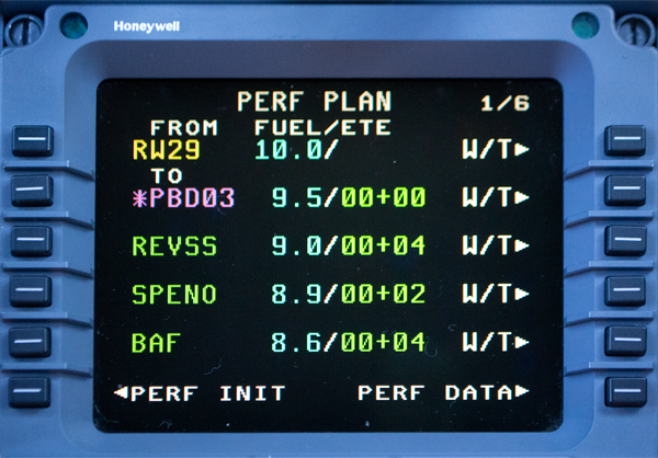
Some FMS will not automatically include downlinked winds and you will have to take steps to ensure the winds are included in the FMS flight plan. A few cautions:
- A downlinked wind may be tied to the flight plan itself and could be hours out of date. You should either update each leg with current winds or downlink current winds if available.
- Entering an average wind might work for some areas of the world but not others. Between Hawaii and California you normally have steady winds, but not always. Between the U.S. and Europe the winds often change dramatically half way across, but not always.
- You should get to know how your FMS adapts to changes in the flight plan with previously downlinked, averaged, or manually entered winds. Some FMS will zero the winds for some types of changes.
See the last part of the story, Flight Lessons / Air Mass, Twenty-three years later for a demonstration on how this can become a very big problem.
MCDU "PERF Plan" page
4
FMS flight plan versus filed flight plan
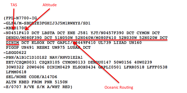
You should check the flight plan that was actually filed versus what is in your FMS, just in case. Even a down linked flight plan could have differences that are important. At some locations the local airport is required to enter the flight plan manually and may give you a copy of what they filed. Use that against your FMS.
Our example trip was filed through ARINCDirect and the last page of the master document includes the filed flight plan. We check that against our primary FMS and are satisfied they are the same.
Master document example, page 5 (filing strip)
5
Filed flight plan verification
Adopt an appropriate symbology to indicate the status of each waypoint listed on the master document. For example:
- The first pilot could circle the waypoint, waypoint number, or symbol on the master document to signify that they have independently cross-checked the entry of the coordinates in the navigation computer.
- The second pilot could then tick or diagonally slash the circled waypoint, waypoint number, or symbol to signify having performed the cross-check to include confirming the course and distance information within a specified tolerance (e.g., plus or minus 2° and 2 NM).
Source: AC 91-70B, ¶6.3.2.7
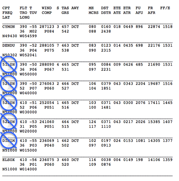
Be especially careful about waypoint shorthand used by the FMS. The ARINC-424 shorthand isn't as intuitive as many pilots believe and it is easy to create your own Gross Navigational Error that can be easily overlooked on the avionics map display. N4550, for example, is 45°30'N 050°W; while 4550N is 45°00'N 050°W, 30 miles south.
More about this: ARINC 424 Shorthand.
- For aircraft equipped with FMS data bases, FMS generated or inserted waypoints should be carefully compared to Master Document waypoints and cross checked by both pilots.
- An appropriate symbology should be adopted to indicate the status of each waypoint listed on the Master Document.
Source: NAT Doc 007, ¶8.2.6
No matter the method used to enter the flight plan, best practices dictate that the other pilot verify the waypoints in the FMS are correct. The waypoint symbology is specified in several documents but personal preferences and company policies may be preferred.
More about this: Waypoint Notation.
Master document example page 2
6
Plotting
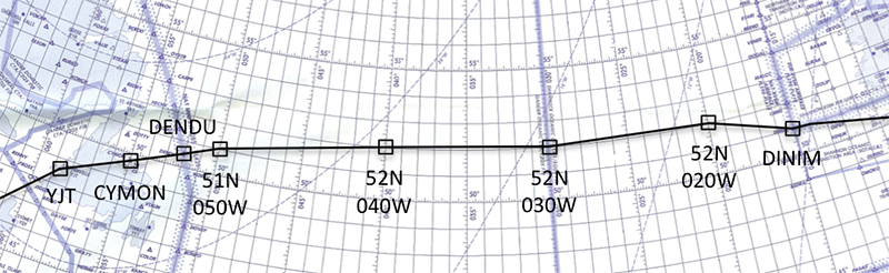
Example plotting chart
The FAA’s Advisory Circular leads you to believe plotting is optional:
Up to now the only recommended method of cross-checking aircraft position in the oceanic airspace environment was manual plotting on a chart. However, a panel of aviation industry and FAA personnel completed an Operational Safety Assessment of methods for cross-checking oceanic flight navigation. Th e panel determined that an alternative to manual plotting, by which aircraft position could be checked through use of aircraft FMS-driven navigation displays and indications, would provide for an equivalent level of safety.
Source: AC 91-70B, ¶6.4.8.2.
But principle inspectors are asked the following to make sure crews are plotting:
Do they require use of a plotting or orientation chart, of adequate scale, for reference/situational awareness purposes?
Source: AC 91-70B, ¶6.4.8.4
Plotting procedures are fairly straight forward but require a level of precision and perhaps some practice. Need a refresher? See: Plotting for some basic instruction.
Plot Relevant Tracks
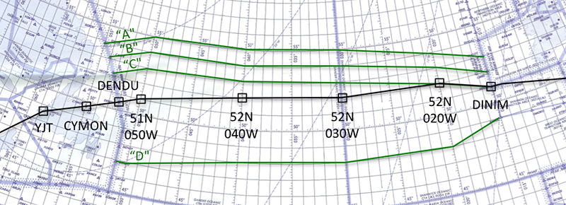
Example plotting chart with track
If your route or any potential diversionary routes cross any relevant track systems, the tracks should be plotted as well. Tracks should be considered relevant if the route of flight is within or over the track system and an aircraft drift down or diversion will conflict any of the tracks. This is especially true over the very crowded North Atlantic (NAT) Organized Track System (OTS).
Flight crews of all NAT flights at or above FL 290, even those that will transit the NAT either above the NAT HLA, or laterally clear of the OTS, must carry a copy of the NAT track message, including any amendments.
Source: ICAO NAT Doc 007, Paragraph 4.1.8
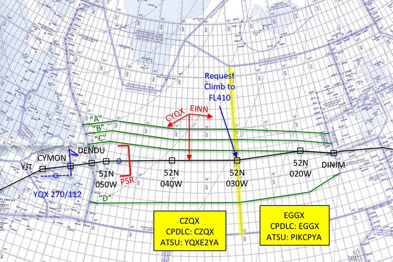
We've plotted all the tracks north of our route of flight, since we will have to cross these should we decide to divert to Iceland. We've also plotted one track to our south, as a reminder about how far we can maneuver if turning right off track.
Master document example page 5
Compute and Plot Equal Time Points (ETPs)
Besides telling you they are needed, there is very little regulatory guidance on Equal Time Points (ETPs). Having an ETP plotted gives you a decision making tool if you find yourself between suitable airports with an engine failure requiring an altitude drift down, a medical emergency requiring a divert without requiring an altitude change, or a loss of cabin pressurization requiring an immediate descent. More about these:
You can calculate your ETP's with pencil and paper, have your flight plan provider automatically compute them, or your aircraft FMS may have an appropriate function. I recommend using the flight plan provider's, at least as a start, since they would be using the same winds as used in the flight plan.
For more about these computation methods, see: Equal Time Points (ETP's).
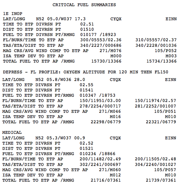
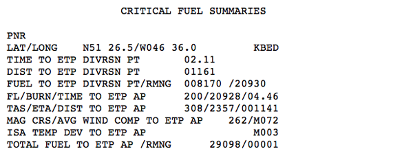
Our flight plan provider includes ETP's on request, as shown in the figure.
The ETP's are plotted with a line off to one side with arrows pointing to the ETP airports. As a technique, if the engine-out, medical, and pressurization loss ETP's are within 100 nm of each other, only the middle ETP need be plotted.
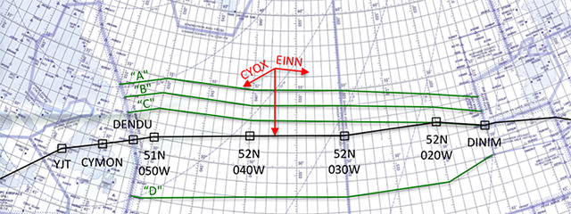
Example plotting chart
In our example, the 1E INOP, DEPRESS, and MEDICAL ETPs are 1510, 1541, and 1521 nautical miles from CYQX, so only the 1521 is plotted. The point is at 52° 05.8'N 37° 00.9'W. Since we know the point will be on our course line, we just need to put our tick mark along the course at 37° 00.9'W. The line is drawn away from the course for clarity and arrows are drawn in the direction of CYQX and EINN.
If we have any reason to divert prior to this ETP, we will choose to reverse course to CYQX. Beyond that point, we press forward to EINN.
Compute and Plot PSRs, if required
Master document example page 5, PNR
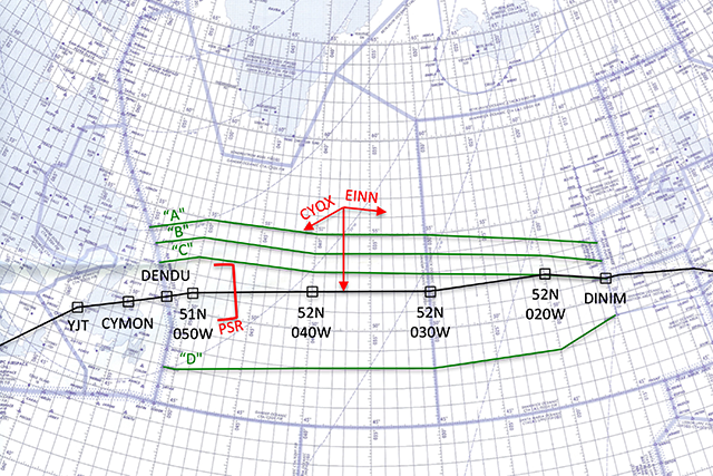
The Point of Safe Return (PSR) provides the pilot with the farthest point to which the aircraft can go and be able to return safely to the departure point with adequate holding, approach, landing, and alternate fuel. It is normally used when flying to remote island destinations with no diversion possibilities en route but can be useful even when alternates are available.
For more about this: Point of Safe Return.
ARINCDirect will provide a "PNR" upon request, as shown. The "Point of No Return" is the same thing as the "Point of Safe Return," with a more dramatic name.
For our example we'll add the PSR and our pre-departure plotting chart preparations will be complete, unless we are using CPDLC / ADS-C, as follows below.
Example plotting chart
If any of our passengers, for some reason, decide they need to go back to our departure airport (KBED), the last moment you can do this without having to make a fuel stop is shown with the red bracket on the chart. Keep in mind that if you return at this point, you will need to fly direct to the airport, the PSR does not use normal routings that anyone less than an emergency aircraft will be offered.
Add CPDLC Addresses, if desired
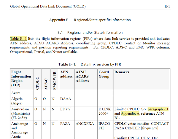
ICAO Gold Appendix E, (ICAO Gold Manual, Appendix E)
You can add the applicable CPDLC FIR boundaries, AFN and ATSU addresses, if you are so equipped and would like the information available on the chart.
For more about this see: CPDLC Preflight Setup.
For our example we'll highlight the FIR boundary between Gander and Shanwick, and enter the addresses found in the ICAO Document 10037, Appendix B.
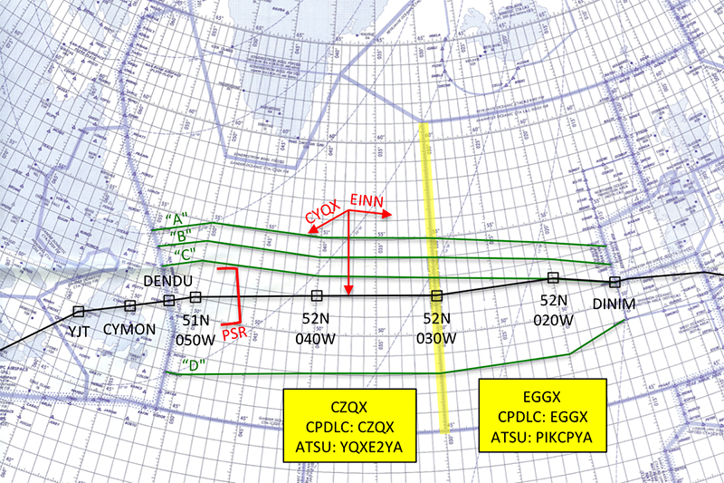
Example plotting chart
Our plotting chart is now ready for the flight.
7
On the ramp
There are a few things that have to be done before you leave the ramp. In fact, with some airplanes, there are things you have to do before engine start. Some of these things are surprises to everyone until the first person spreads the word. In the G450, for example, if you takeoff with the SELCAL codes deleted, you cannot recover them in flight. So you might as well check them before you leave the chocks.
Master document, ramp
UTC Time Check.
You must have an identified master clock on board synchronized to Coordinated Universal Time (UTC) (generally via GPS). You must use this single time source, typically the FMS, for all ETAs and ATAs.
Source: AC 91-70B, ¶D.2.2.1
You can use your HF, your GPS, or an Internet source.
More about this: UTC Time Check.
Fuel Check.
Record fuel onboard on the Master Document; this quantity will become the basis for subsequent fuel checks.
Invert Flight Plan
If you think you might want to have your "go" flight plan in reverse, a "return" flight plan, and if your FMS gives you the option of inverting the flight plan, before you leave the chocks would be a good time to do that. In the G450/G550, you cannot do this once you've left the chocks. For these aircraft, you scroll to the bottom of the flight plan and give it a name. Then, if you need it later during the flight, you select the "NAV INDEX" key, the "FPL LIST" key, and then select your named flight plan, and then "INVERT/ACTIVATE" from the menu.
Domestic Clearance
You will typically have a domestic clearance that will include your destination but not the oceanic portion of the trip. Your clearance at this stage does not normally give you clearance into oceanic airspace.
Our domestic clearance is: "Gulfstream seven seven zero zero is cleared to Geneva via radar vector Lobstah then as filed. After takeoff maintain runway heading and climb to two thousand feet, expect flight level four three zero ten minutes after takeoff. Contact departure control on one two four point four, squawk four three two one." We are clear to our destination but we do not have clearance into oceanic airspace.
SELCAL Configuration
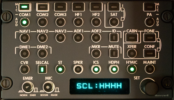
G450 audio control panel SELCAL setting
Some aircraft encode their SELCAL codes in software and may lose the code on occasion. In the G450, for example, the code can be entered from any cockpit audio control panel but only when on the ground. It is a good idea to make sure the code is entered and correct when you can.
Altimeters.
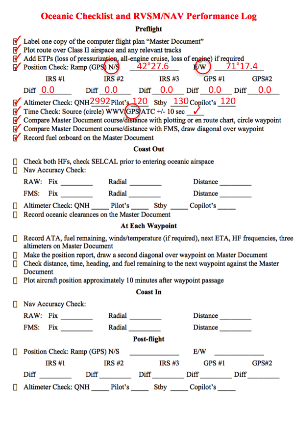
RVSM/NAV performance log example, preflight
Before taxi, you should set your altimeters to the airport QNH. Both primary altimeters must read within ± 75 feet of field elevation. The two primary altimeters must also agree with each other within the limits noted in the aircraft operating manual.
Source: AC 91-70B, ¶D2.2.4
Groundspeed Check.
Groundspeed check. You should note the groundspeed before taxiing the aircraft. You should expect the groundspeed to read zero knots. Note: This procedure is a good practice to detect an error that may be developing in the LRNS.
Source: AC 91-70B, ¶D.2.2.12
An inertial ground speed while stationary is an indication there is significant drift in the unit. Some aircraft offer a "quick align" to reset the inertial's ground speed to zero. In older Gulfstreams, for example, switching from NAV to ALIGN to NAV in less than six seconds causing such a quick align. Other aircraft with Hybrid IRS, such as the G450, automatically perform a quick realign any time the aircraft is motionless for more than 7.5 minutes.
RVSM/NAV Performance Log.
You should have a log to record your altimeter and navigation system performance so that you remember to check all that needs to be checked, and so that you have a written record of it. A blank log is available for download: here.
More about the requirement: Oceanic Arrival / Record Keeping.
CPDLC Checklist
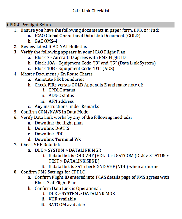
CPDLC checklist example
If you are CPDLC-equipped and departing into an area with CPDLC coverage, you have several steps to accomplish while still sitting on the ramp. It may be helpful to add a printed copy of your CPDLC checklist to the RVSM/NAV Performance Log and Master Document.
More about this: CPDLC Checklist.
Local Procedures Review.
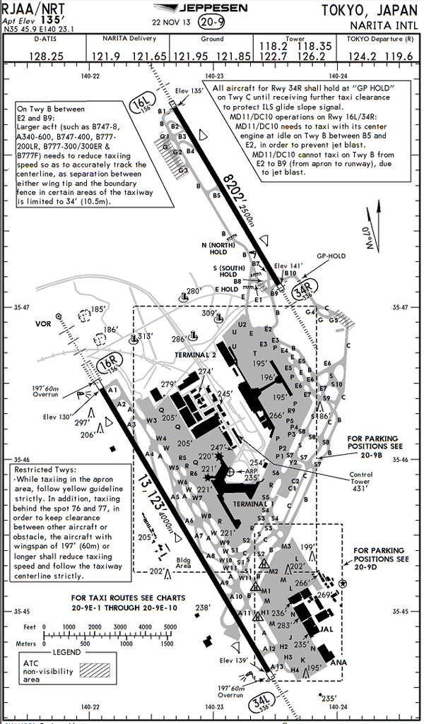
Narita airfield diagram, (Jeppesen Airway Manual, Narita Intl, RJAA, 20-9, 22 Nov 13)
The Jeppesen Airway Manual approach charts for the airport may have several pages of local procedures that should be reviewed prior to request for clearance or engine start. These procedures can include specific instructions that are critical to successfully operating at the airport, such as:
- Engine start procedures
- Clearance delivery procedures
- Start-up, push-back and taxi procedures
- Noise abatement procedures
- Speed restrictions on departure and arrival
- Runway entry and exit procedures
If you are sitting at an unfamiliar airport, foreign or domestic, it always pays to listen to the ground control or tower frequencies for a while to get the "lay of the land" and a heads up as to your immediate future. A few things to listen for:
- Is ground control giving ATC clearances before taxi? (That is not the normal procedure for most of the world but the list of exceptions are growing. If they are giving ATC clearance that is what you ask for, "Request ATC clearance."
- Which departure procedures are in use? At locations where advance ATC clearance is not given, you will be listening to your ATC clearance while your are taxiing, just minutes away from takeoff. You will often have a difficult time understanding what the departure procedure is and it will be to your benefit to have an idea early on. Some airports group departures based on the runway in use, for example.
- Taxi routings can include instructions you've never heard before. You may hear other aircraft instructed to "Holding Point Whiskey" but not see that immediately on any charts. Hearing this given to another airplane gives you some time to look it up.
Oceanic Clearance Prior to Departure
You normally request your oceanic clearance while airborne, see: Oceanic Clearance, but there are exceptions for some airports that are close to oceanic airspace. For example:
NAT flights departing Irish aerodromes excluding Dublin, Weston and Casement (Baldonnel) airports, planned to enter NAT airspace between GOMUP and BEDRA (inclusive) should request Oceanic Clearance from Shanwick Oceanic via ORCA Datalink prior to departure. Shannon ACC will on request obtain Oceanic Clearance from Shanwick Oceanic and pass the clearance to the flight prior to departure.
Source: Jeppesen Airway Manual / Air Traffic Control / State Rules and Procedures - Ireland
If you are departing from an airport that is near the oceanic airspace you will be transiting, you should check the applicable Jeppesen Airway Manual page for a requirement to obtain oceanic clearance prior to departure.
8
Prior to oceanic boundary / oceanic clearance
Depending where in the world you are, much of your tasks prior to the oceanic boundary can be done after takeoff, or must be done prior.
Departure Timing.
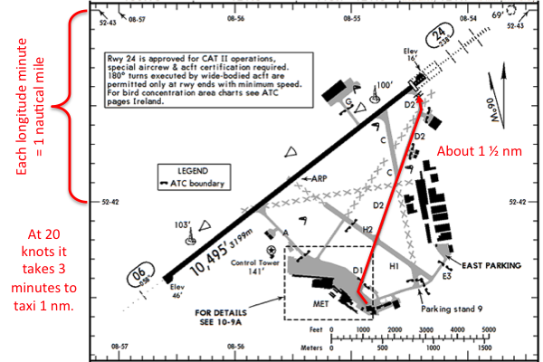
Shannon airfield diagram, (Jeppesen Airway Manual, Shannon, EINN, 10-9, 14 Oct 13)
Time to Taxi. If assigned a wheels up time or a time crossing your first oceanic point, you may need to carefully plan when you plan leaving the chocks. You can estimate your taxi time using the airfield diagram:
- Scale: The longitude scale should include the degree minutes in the format degree - minutes. 46-14, for example, means 46°14'. Each minute of longitude equals one nautical mile.
- Distance to Taxi: Using that scale, you can estimate the distance from your parking stand to the runway holding point.
- Time to Taxi: If you taxi at twenty knots, you will cover each nautical mile in 3 minutes. Remember to add a few seconds for each turn as you will probably slow a bit.
In the example Shannon Ireland diagram shown, we build a scale using the 52-42 and 52-43 longitude marks and determine our distance from the apron to the holding point for runway 24 is 1½ nautical miles. At 20 knots that will take 3 x 1½ = 4½; let's call it 5 minutes to account for the turns. We know it takes about 5 minutes to get the engines started and to complete all before taxi checklists, so we plan to start engines 10 minutes prior to our projected wheels up time.
Time to climb - FMS Capable. A modern FMS should give you an accurate ETA to your first oceanic waypoint if you input the estimated takeoff time.
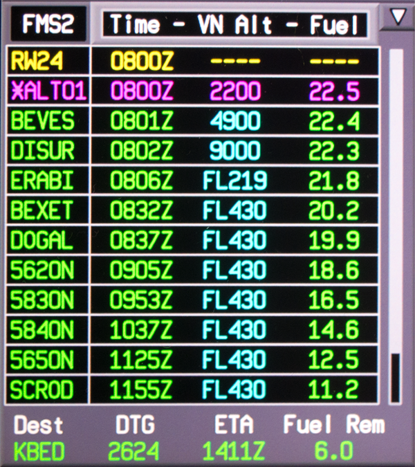
G450 Flight Plan 1/6 page,
If in EINN, for example, expecting the ERAB2B departure to ERABI, BEXET, DOGAL, and then oceanic routing, you can enter expected takeoff times and see the ETA for each point update. If your oceanic clearance stipulates a 0837Z time overhead DOGAL, you can subtract the FMS time at DOGAL from the planned departure time to come up with an ETE, then use that to adjust the departure time. For our G450, we see it takes 37 minutes, so we enter /0800Z at LSK 1L on the first page of the flight plan. The FMS computes we will reach DOGAL at 0837Z. Now we know we must takeoff at 0800Z to make that happen.
Time to climb - FMS Not Capable. Some older FMS will not correctly compute ETAs during or following a climb to altitude. In the older GIIIs, for example, the FMS assumed 250 knots ground speed until level off, which was way too slow. We found adding 5 minutes to the ETA for any point between FL 300 and FL 350 plus an additional 1 minute per every additional 5,000 feet worked well. Of course that was for the GIII, you will have to experiment to find a rule for your FMS.
Transition Altitude.
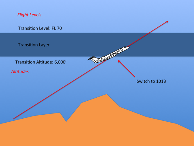
Transition layer climb
- Transition altitude: The altitude at or below which the vertical position of an aircraft is controlled by reference to altitudes.
- Transition Level: The lowest flight level available for use above the transition altitude.
Source: ICAO Document 4444, Ch 1
Crews should brief the transition altitude based on information from approach plates, ATIS, or the applicable state pages. After climbing through the transition altitude, the altimeters should be reset to 29.92 inches or 1013.2 hPa.
Some avionics can be programmed to remind you when you are passing the transition altitude or layer. The G450 FMS, for example, has a transition level function on the PERF INIT page that is normally set to 18,000 feet. Changing the level will change when you receive a "CHECK BARO SET" message if the altimeter hasn't been changed after passing 1,000 feet of the entered altitude.
More about this: Transition Altitude/Layer/Level.
Climb Level-off Procedure.
To prevent unwanted TCAS/ACAS warnings or alerts, when first approaching any cleared flight level in NAT RVSM airspace, pilots should ensure that the vertical closure speed is not excessive. It is considered that, with about 1500 ft to go to a cleared flight level, vertical speed should be reduced to a maximum of 1500 ft per minute and ideally, to between 1000 ft per minute and 500 ft per minute. Additionally, it is important to ensure that the aeroplane neither undershoots nor overshoots the cleared level by more than 150 ft.
Source: NAT Doc 007, ¶9.1.10
This seems to be necessary more in Europe than in the United States. Perhaps the skies are more crowded or there is an abundance of older TCAS software. Whatever the reason, reducing climb rates near level off appears to be necessary.
En Route Timing.
If en route to the waypoint with a timing restriction, you can make minor adjustments with speed, larger adjustments with routing changes. If late more than a few minutes you may need to get a reclearance.
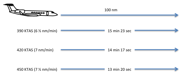
Timing 30 knots adjustment
Adjusting speed — If flying at typical en route speeds, it will take about 100 nm to impact your ETA by 1 minute if adjusting by 30 knots.
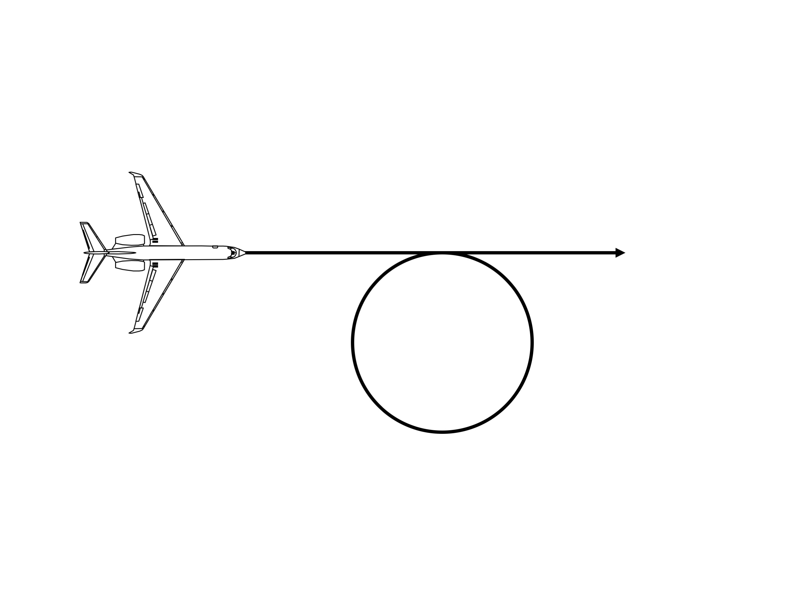
Timing standard rate
360° Turn — A half-standard rate turn takes 4 minutes.
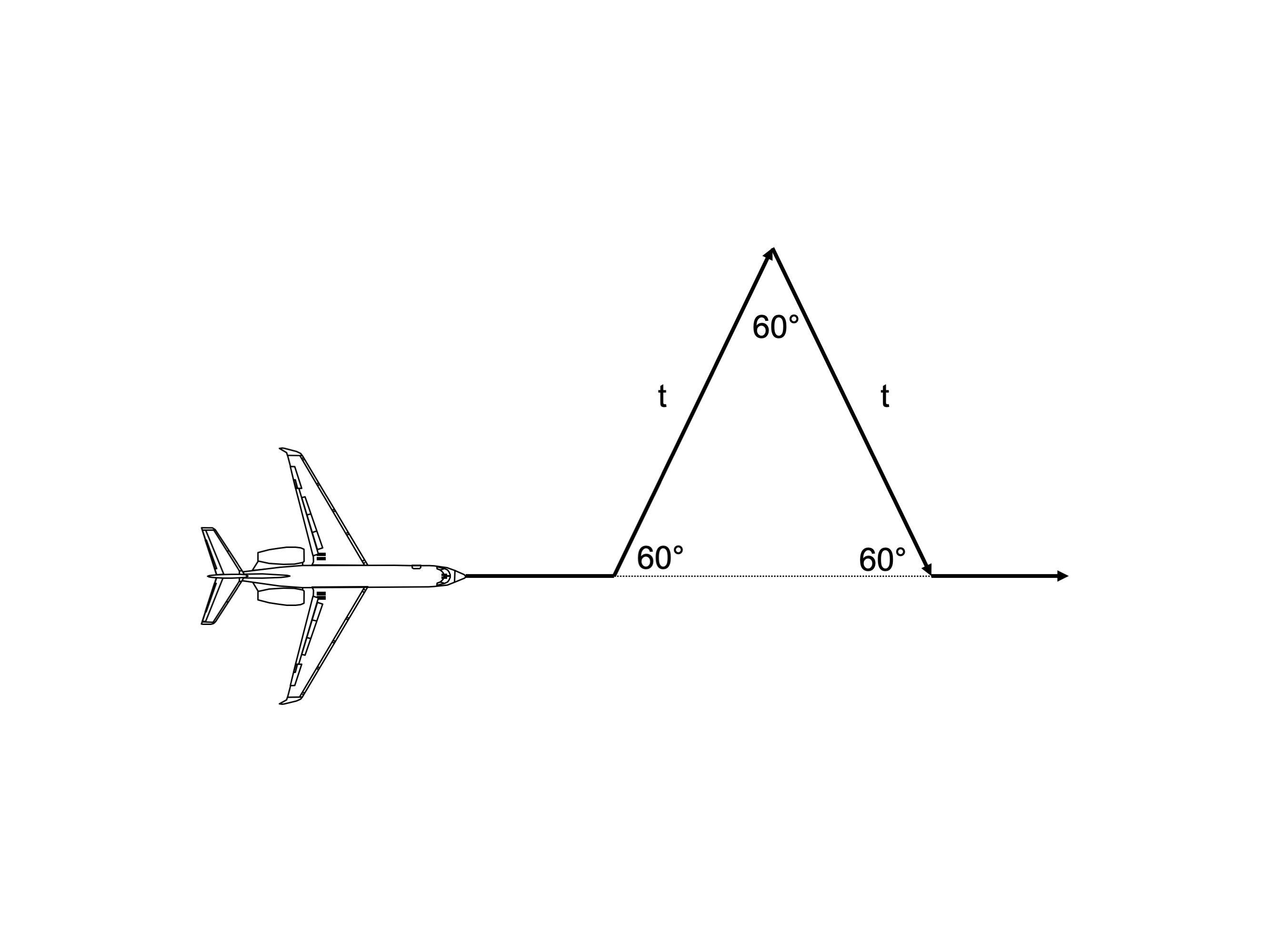
Timing triangle
Timing Triangle — A turn 60° off course, followed t-seconds by a turn 60° back towards course, followed t-seconds later by a turn back onto course costs a total of t-seconds.
More about these timing techniques: Block Times.
HF Radio.
HF Check.
- You should conduct an HF check on the primary and secondary HF radios in areas where dual HF radios are required. (Two long-range communications systems are typically required for oceanic and remote continental airspace operations.)
- If possible, you should accomplish the HF checks on the ground or before entering oceanic airspace.
- Even if you are data link equipped, you should accomplish a SELCAL check at each oceanic control area boundary.
Source: AC 91-70B, ¶D.2.2.8
Proper HF frequency selection can be a challenge in some regions and is not always facilitated by VHF center controllers when leaving domestic airspace. In general the regional en route chart can be a good source of frequency information. Here are two great sources:
https://radio.arinc.net/atlantic/
https://radio.arinc.net/pacific/
More about this: HF.
CPDLC / ADS.
If CPDLC and/or ADS-C are available for flight, you should logon as follows:
- When operating outside data link airspace, the flight crew should initiate a logon 10 to 25 minutes prior to entry into airspace where data link services are provided.
- Where a data link service is only provided in upper airspace and where local procedures do not dictate otherwise, the flight crew should log on to that ATS unit in whose airspace a data link service will first be used.
- When failure of a data link connection is detected, the flight crew should terminate the connection and then initiate a new logon with the current ATS unit.
Note.— When departing an aerodrome close to or within such airspace, this may require the logon to be initiated prior to departure.
Source: ICAO Doc 10037, ¶4.2.2
Greater detail here: CPDLC.
Oceanic Clearance
Master document, oceanic
Obtain Oceanic Clearance.
- At least two pilots should be involved in the clearance receipt and read-back process, one actively and one monitoring. When obtaining the clearance via radio, we recommend both pilots wear headsets because errors have resulted from loudspeaker distortion.
- Consult the AIP for the oceanic airspace FIR you are transiting to determine how and when to obtain your oceanic clearance. Timing differs depending on whether you receive your clearance via voice or data link.
- Both pilots should independently copy the clearance. Each pilot then cross-checks and verifies with the other pilot the routing, FL, and Mach number assigned for the crossing. If there are any differences, contact the ATS provider for clarification.
- Read all waypoint coordinates back to the ATS provider in detail. Ensure the ATS provider acknowledges your correct read back. Always cross-check each detail of the clearance with your master document.
- It is important that both pilots confirm and ensure the aircraft enters the oceanic airspace at the altitude assigned in the oceanic clearance (this may be different than the domestic cleared FL). Request climb or descent, as required, in order to be at your cleared oceanic FL prior to entering oceanic airspace.
Source: AC 91-70B, ¶D.2.5.6
Re-Clearance.
- The number one scenario that leads to a pilot deviation from the assigned routing is a reclearance (that is different from the oceanic route requested with the filed flight plan).
- You should be particularly cautious when receiving a reclearance.
- Both pilots should separately copy and confirm the new routing, comparing with each other and confirming any inconsistencies with the ATS provider.
- One pilot reprograms (and executes) your LRNS and updates the master document and plotting/orientation chart, crossing out the old waypoints and plotted route and replacing them with the updated information.
- A second pilot cross-checks the newly effective route clearance with the reprogrammed route in the FMS (checking the expanded coordinates: degrees and minutes), the updated master document, and the updated chart.
Source: AC 91-70B, ¶D.2.5.7
A few notes about oceanic clearances:
- CPDLC (Everywhere except NYC) — If you are CPDLC- or ACARS-equipped in any region other than the NYC FIR you can downlink your oceanic through a data link service provider.
- CPDLC (NYC FIR) — If you are CPDLC in the NYC FIR, you can downlink your oceanic clearance directly through CPDLC.
- Voice Procedures (Gander) — Panel 1 of the Jeppesen Atlantic Orientation Chart includes Gander OCA procedures and frequencies needed to obtain an eastbound oceanic clearance.
- Voice Procedures (Shanwick) — Panel 11 of the Jeppesen Atlantic Orientation Chart includes Shanwick OCA procedures and frequencies needed to obtain oceanic westbound clearance.
See: CPDLC - Oceanic Clearance (DSP).
See: CPDLC - Oceanic Clearance (NYC).
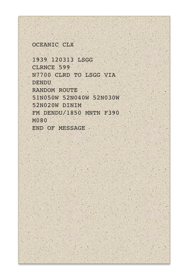
Oceanic clearance downlink
We receive our clearance via data link and notice that we have been cleared at FL 390, which is a bit unusual for us. A quick glance at the flight plan reveals that we are too heavy to cross any higher but there is a plan to climb to FL 410 passing 030W. Of course the flight plan accounts for this but what if, for some reason, we don't get clearance to climb? A quick look at the fuel burns tells us we are okay even if the entire crossing is made at the lower altitude, but just the same we made a note on the plotting chart to remind ourselves to request a climb.
SELCAL Check.
Even if you are data link equipped, you should accomplish a SELCAL check at each oceanic control area boundary.
Source: AC 91-70B, ¶D.2.2.8
The SELCAL check is more than a test of your radio equipment, it is a test of the complete connection from your airplane to the radio station. You need to check it every time you change frequencies or FIR. If you are unable to get a good SELCAL check, you must maintain a listening watch on the frequency, even if you are CPDLC equipped.
Coast-Out Navigation Accuracy Check.
- Before oceanic entry, you should check the accuracy of your LRNS against a suitable ground-based NAVAID, as applicable. A latitude/longitude radar fix from ATC can also support a navigation accuracy check in lieu of a NAVAID.
- You should record the results of the accuracy check on the master document, with the time and position.
- A large difference between the ground-based NAVAID and your LRNS, such that the ability to navigate with the accuracy required by ATC is questionable, requires immediate action, to include notification of ATC prior to entry into oceanic airspace.
- You should establish a navigation accuracy check tolerance based on your type of LRNS. Rank each navigation system by accuracy if applicable.
- Record aircraft compass/inertial/radio magnetic indicator (RMI) headings and note differences and deviations. A compass deviation check is particularly important if your aircraft is not equipped with an FMS.
- Select the most accurate navigation system for autocoupling as appropriate.
Note: Crews should not attempt to correct an error by performing an air alignment or by manually updating the position of the LRNS, because this has often resulted in worsening the problem.
Source: AC 91-70B, ¶D.2.5.1
Before you stray out of ground-based NAVAID range — sooner actually, before you leave the service volume of an appropriate NAVAID — you need to compare what it is telling you versus what your FMS is telling you. The procedure can be checking a VOR Radial/DME plot versus your FMS latitude/longitude on your plotting chart, or using an FMS "Cross Points" function versus the VOR Radial/DME.
More about this: Navigation Accuracy Check.
Prior to Oceanic Boundary Altimeter Check.
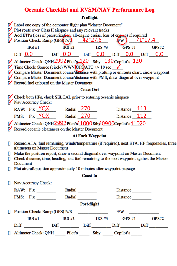
RVSM/NAV performance log example, coast out
Altimeter Checks.
- Prior to oceanic entry, you must check the two primary altimeters are reading within 200 feet of each other (or lesser value if specified in your aircraft operating manual). Conduct this check while at level flight.
- You should also note the stand-by altimeter reading.
- Record the altimeter readings along with the time on the master document.
Source: AC 91-70B, ¶D.2.5.8
More about this: Loss of RVSM Capability in Oceanic Airspace.
In our example flight from KBED to LSGG we have complete all the necessary tasks to enter oceanic airspace and our plotting chart reflects that:
Example plotting chart (just entering oceanic)
9
Letter from a reader
Dear James,
We were flying in Australian airspace the other day when center asked us to cross the next waypoint at a certain time. How do you do that? We couldn't find anything in the FMS to help us.
Signed, R. Fader
Fort Lee, New Jersey
Dear Mister Fader,
I've never used an FMS that does this automatically. You simply have to look at the ETA your FMS gives you and adjust your speed or your route until the ETA is correct. Of course this is easier said than done.
When speeding up your options are limited by the top speed your aircraft will do and this can be limited by your VMO, MMO, or other constraints such as turbulence or the airplane's RVSM limitations. This, of course, means there could be some math involved. I'll go through the math, but if you just want the procedures, look at the "Rules of Thumb" given.
James
When en route, making pure, brute force changes to airspeed is usually the first option when adjusting.
Speed of sound = 573.8 nm/hour (above 36,000 feet)
Which means:
It is helpful to know in advance how much speed you can gain by going as fast as you would normally want versus your normal cruise Mach, as well as how much you can lose my slowing as much as you would be comfortable doing at altitude. Say, for example, you normally cruise at M 0.80 and are willing to fly as fast as M 0.83.
So that means we can cover the distance traveled in an hour at the original speed (459 nm/hr) more quickly:
Multiplying by 60 converts that to minutes:
So speeding up by M 0.83 covers the same distance originally flown in 60 minutes in a time of 58 minutes. I'll leave the math up to you, but slowing down by M 0.03 will take 62 minutes.
You can do the same thing for other increments, if your aircraft allows it. Say, for example, you want to be able to speed up to M 0.85 or slow down to M 0.75. You will find that will gain or lose you 4 minutes.

Timing: You can gain or lose two minutes by speeding up or slowing down by M 0.03
It is easier to lose time than gain it, obviously. To lose 2 minutes at lower altitudes you can make a standard rate 360 degree turn. At higher altitudes, you may have to settle for a half-standard rate because of bank angles, but that loses you 4 minutes.
A 360° turn
Timing: A standard rate 360 degree turn loses 2 minutes, a half-standard rate 360 degree turn loses 4 minutes.
For larger losses, a timing triangle can be used by flying 60 degrees off heading by the amount of time to be lost, then 60 degrees in the opposite direction, then 60 degrees back on course.
A timing triangle
Timing: A 60 degree turn off course for time t followed by a 60 degree turn back to course for time t and a 60 degree turn back on course will add time t to the en route ETE.
References
(Source material)
Advisory Circular 91-70B, Oceanic and International Operations, 10/4/16, U.S. Department of Transportation
ICAO Doc 4444 - Air Traffic Management, 16th Edition, Procedures for Air Navigation Services, International Civil Aviation Organization, October 2016
ICAO Document 10037 AN/509 - Global Operational Data Link (GOLD) Manual, Advance edition (unedited), First Edition, 2016
Jeppesen Airway Manual
ICAO Nat Doc 007, North Atlantic Operations and Airspace Manual, v. 2021-1, applicable from February 2021