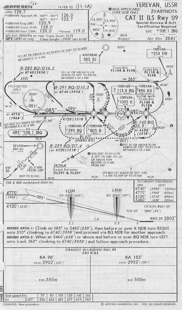
I shot the approach shown here in 1992, back in the bad old USSR, during a shooting war between Armenia and Azerbaijan. The airport sits just north of Mount Ararat, the place where Noah's Ark is supposed to be, hence the very high MSAs. Oh yes, I was getting a check ride. The weather was above minimums, but not by much. The good news is that the approach was well designed and when we broke out there was runway in front of us. It doesn't always work out that way.
— James Albright

Updated:
2015-10-01
Over the years I've seen more than my share of instrument approaches that left me wondering what the approach designers were thinking, if air traffic control was trying to set me up, or if I had simply dreamt up my instrument rating and really didn't know what I was doing.
So here we go, a few examples that I hope will help you figure out when either the approach designers or air traffic controllers do not have your health and well being in mind. If you are here without an instrument rating, well you can figure the solution to that.
All of this is hard-learned technique. (No references provided.)
2 — Legal (but impractical) approach
3 — Circling (just about all of them) approach
4 — Mountainous straight-In (many of them) approach
There is a fair amount of math involved here. Back in the days before flight management systems and flight directors we pilots were responsible for a lot of math. Now the computers do that but they haven't done a thing to prevent the problems shown in these example approaches. If you are an airline pilot chances are somebody already looked at the approach and gave it the airline's blessing. This is called approach validation. If you are a corporate pilot, chances are the person doing the approach validation is you. If you want to do a proper job of this, you will need to know:
How to compute your aircraft's turn radius. See: Turn Performance for a discussion about how to do this.
How to compute a descent angle. See: 60 to 1 (Math is Hard) for a story about this and 60 to 1: Engineer to Pilot Translation for more.
Of course you may already have some knowledge here and just need a few formulas. I've provided a cheat sheet below: Instrument approach math. I've had this cheat sheet hanging on my wall for many years now. I do more math than most, but as my hair grows gray my brain doesn't remember these things the way it used to. But if you are an approach validator, these things are necessary.
1
Poor approach design
Example: Kingston, St. Vincent (TVSV)
If you ever get a chance to turn down a trip to E. T. Joshua Airport (TVSV) in St. Vincent, you should jump on that. I've been there once and wish I had never seen the place. It is a short runway (4,649') that sits at the edge of a mountain. The only instrument approach is an NDB that makes no sense whatsoever. Unfortunately, I never figured that out until after I flew there. Once I figured it out, I said no to further trips. But it remains as a good example of how a poorly designed approach can fool you. (It fooled me.)
UPDATE: The good folks at St. Vincent closed the airport and took their business to the other side of the island, so you won't have to shoot this approach. But it still provides a good example an an impossible approach.
First Look
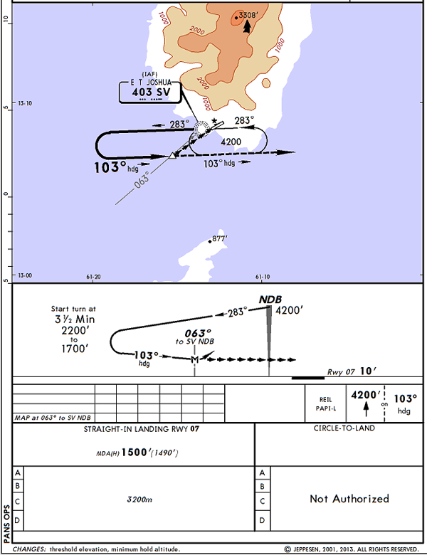
TVSV NDB Rwy 07 planview, profile, and minimums,
from Jeppesen Airway Manual, pg. TVSV 16-1, 2 Aug 13.
At first glance it looks okay. You head outbound from the IAF for 3-1/2 minutes and if you fly that at the same speed you make the turn, your offset should be good enough. I thought the GV was the perfect airplane for the job. Not only did we have a very low approach speed for the runway, that approach speed would give us the tightest possible turn radius. We flew this thing perfectly in our GV, 120 KCAS outbound, in the turn, and intercepting the final approach. But we didn't realize there was a problem.
Before you scroll down, look at the approach plate and try to see if you can spot the problem.
Planview
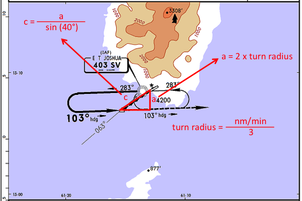
TVSV NDB Rwy 07 planview, with drawn triangle, from Jeppesen Airway Manual, pg. TVSV 16-1, 2 Aug 13.
If you make a standard rate turn your turn radius should be equal to:
In the case of a GV traveling at 120 KCAS (2 nm/min):
Which of course means your turn diameter is twice that, so the distance a in the drawing is 4/3 nm. The hypotenuse of that triangle is what we are interested in. How much distance do we have to make our descent from the MDA to the runway?
In the case of our GV doing 120 KCAS:
That seems like enough, but is it?
Profile View
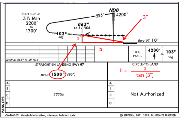
TVSV NDB Rwy 07 profile view, with drawn triangle, from Jeppesen Airway Manual, pg. TVSV 16-1, 2 Aug 13.
The approach appears to keep you at the MDA of 1,500' until making the 063° turn to the runway. Since we want a 3° glide path whenever possible, we need to begin the descent:
In the case of an MDA of 1,500':
No wonder we could never make the approach work! You cannot fly it with a hard MDA, it has to be flown as a visual. There is another problem with using this approach under instrument conditions. The visibility required is 3,200 meters, which comes to 1.7 nautical miles. You could find yourself shooting this approach with legal visibility with no possibility of landing in a controlled manner. (It would take an 8 degree descent rate from the MDA.)
Conclusion & Lesson Learned
This is not a circling approach but it is not a properly designed straight-in approach either. If you had to fly to this runway, I would insist on VMC conditions with at least 5 nm (5.75 sm) visibility.
The lesson here is that if the approach looks unusual, it might be. If you've never seen the design before you should consider a "chair flying" session where you imagine your airplane in each phase of the approach and consider the problems with safely getting to the next phase.
2
Legal (but impractical) approach
Example: Amsterdam, Netherlands (EHAM)
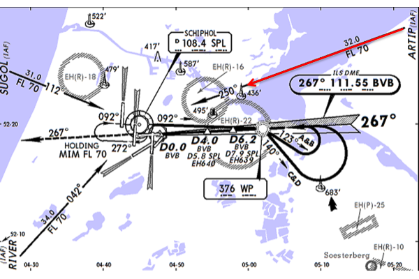
EHAM ILS DME Rwy 27 Planview,
Initial Clearance,
from Jeppesen Airway Manual, EHAM 11-7, 16 Sep 11
Approach as depicted
An ICAO Course Reversal must be entered in a specific corridor and if outside that corridor there may be a holding pattern that gives you the opportunity to reverse course twice. Here is an example I've flown recently.
The ATIS was one line long with winds, temperature, ceiling, visibility and instructions to expect the ILS to Runway 06. After we checked in with approach control we were cleared "ARTIP ILS DME RWY 27" and that was it.
Visual approaches are not allowed. What would you do?
Approach as intended (and expected)
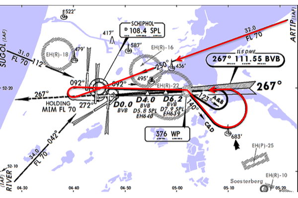
EHAM ILS DME Rwy 27 Planview, Initial Clearance, from Jeppesen Airway Manual, page EHAM 11-7, 16 Sep 11
If you are not within a specific entry sector under ICAO Course Reversal rules, you must proceed to the holding pattern, execute one turn, then execute the course reversal as depicted. Yes, you are reversing course twice. More about this: Course Reversals.
The EHAM Airport Briefing pretty much spells this out in the case of lost communications, but it also says "navigation in the initial and intermediate approach segment is primarily based on radar vectors by ATC."
You must reduce to 220 Knots within 15 nm of SPL and be prepared to fly the entire procedure.
Approach as usually given
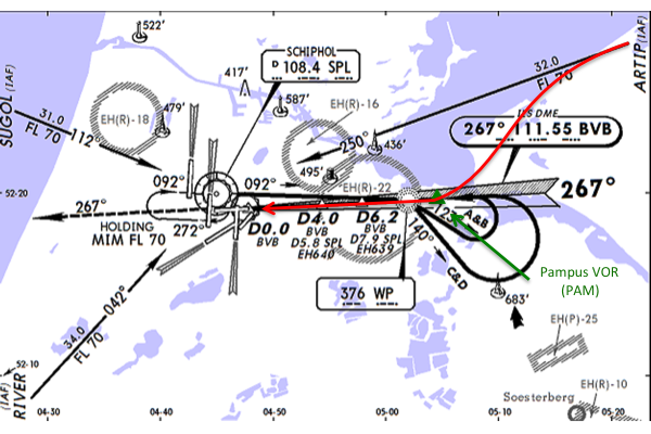
EHAM ILS DME Rwy 27 Planview, Initial Clearance, from Jeppesen Airway Manual, page EHAM 11-7, 16 Sep 11
While you must be prepared to fly the entire procedure do not delay other cockpit tasks thinking you have ten minutes to spare. You will very likely be given vectors or clearance "Direct Papa Alpha Mike, cleared the ILS DME Runway 27." You need to be ready to descend and configure quickly.
Conclusion & Lesson Learned
There is nothing wrong with this approach, other than it wastes time and congests the skies over an already congested airport. Knowing the proper procedure prepares you if the controller gets too busy or forgets the last minute change. But you need to be ready for that change as late as it might come.
The lesson here is to understand the operating rules of your environment; you should not fly any instrument procedure outside the United States until you understand ICAO course reversal rules. Once you've done that, you need to be able to predict "what is expected" versus "what is depicted."
3
Circling (just about all of them) approach
Example: JFK, New York KJFK
Just about every circling approach at minimums is impossible to complete with a stable approach on final. More about this: (U.S.) Circling Approach Visibility Minimums (Are Too Low!).
Ever wonder why you normally demonstrate your circling abilities in a simulator wired to KMEM LOC 27 circle Runway 18R or to KJFK Loc 4R circle Runway 31R? It is because they both have a runway perpendicular to the landing runway which is offset, giving you extra distance and improving your odds. The chances of having to really circle at either of these airports is quite low. But even with the help of another runway to help keep sight of the airport environment, you will still not be able to roll out at 500' above the runway on a 3° glidepath if the visibility is at minimums. For example . . .
The Normal Quick Look
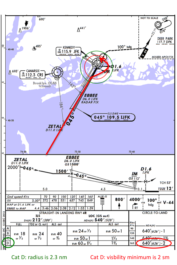
KJFK ILS or LOC Rwy 4 planview and minimums,
circling to Rwy 31R depicted, from
Jeppesen Airway Manual, KJFK 21-2, 22 Nov 13
The minimum Category D obstruction clearance radius for circling approaches under older TERPS criteria is 2.3 nautical miles. The minimum visibility allowed for a Category D approach under U.S. rules is 2 statute miles. Keep in mind that comes to only 1.74 nautical miles.
If you typically brief "I will commence my circle at 2.3 miles" (the green circle on the accompanying approach plate) you shouldn't be surprised if it takes you a bit longer to spot the runway. How much longer? It will be 2.3 - 1.74 = 0.56 nm. Yes, we just robbed you of more than a half a mile.
This might explain why this circling approach seems more difficult in actual practice than it does in theory. But so what, you say, you will just have to keep the airplane a half a mile tighter. Not a big deal, right?
Stable Approach Impossible
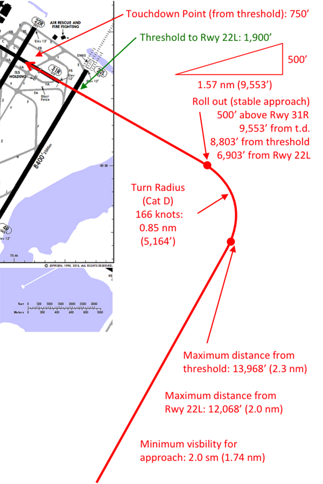
KJFK airport diagram extract, circling to Rwy 31R depicted, from Jeppesen Airway Manual, page KJFK 20-9, 14 Aug 15
If you want to land in the touchdown zone your aim point will be 750' from the threshold.
A 3° glide path requires 318' per nautical mile, which means you need to be wings level no later than 500 / 318 = 1.57 nm (9,553') from touchdown. The usual way to measure that is from the runway threshold, which makes it 9,553 - 750 = 8,803' from the threshold. Of course this isn't a normal runway layout, we have the added benefit of Runway 4R/22L to help keep sight of the airport. The edge of that runway is 1,900' from the threshold of Runway 31R, meaning we only have to roll out 8,803 - 1,900 = 6,903' from that runway.
A Category D aircraft flying at the maximum category speed will be doing 166 knots and will have a turn radius of 5,164' under no-wind conditions at sea level. That means the maximum distance from the airport environment (Runway 4R/22L) will be 12,068' and that comes to 2 nautical miles.
But the minimum visibility for the approach is 2.0 statute miles, which is only 1.74 nautical miles!
The numbers are just as bleak for a Category C aircraft which can maneuver in only 1.7 nautical miles but is only given 1.75 statute miles (1.49 nautical miles) visibility.
Conclusion & Lesson Learned
Circling at minimums is demanding even under ideal conditions. But for most conditions where a 90° or greater turn involved, it can be impossible. Newer TERPS criteria that bestow the "inverse C" on an approach give you more maneuvering area but do nothing about the minimum visibility criteria.
The lesson here is a simple one: don't circle at minimums. How low can you go? See (U.S.) Circling Approach Visibility Minimums (Are Too Low!) for a technique to determine realistic minimums.
4
Mountainous straight-In (many of them) approach
Example: Eagle, Colorado (KEGE)
The first time I flew into Eagle, Colorado was in an Air Force GIII that did not have an EGPWS, GPS, or just about any other of the niceties we take for granted these days. We briefed that if we didn't see the runway at the point now called POWRS, we would go someplace else. If we did spot the runway, we would fly down the valley.
Years later, in a high tech CL-604, I was in the right seat and watched with dismay as the pilot (also the chief pilot and my boss) flew right down the centerline of the approach. Our first EGPWS warning was over the 9,036' peak. Then we got a few more as his VVI exceeded 1,000 fpm one or two times. After that, I convinced him and our other pilots that the valley was the way to go. (We also got very familiar with an excellent airport just a few minutes to the west, Rifle, Colorado.)
There is much to be learned about how to diagram an approach with this example . . .
A Lot of Mountains
-d.png)
KEGE RNAV(GPS)-D, from Jeppesen Airway Manual,
page KEGE 12-1, 22 May 15
Looking at the approach plate there are obviously a lot of mountains but one can be forgiven for thinking this approach meets TERPS criteria so it can't be too bad. Right?
The descent rates from POWRS to AWACC and from AWACC to NEPRY are not too bad, certainly within all guidance. But what about the rate from AWACC at 11,100' down to the runway at 6,547'? The distance between those two points is 7.5 nm so the descent rate is (11,100 - 6,547) / 7.5 = 607' / nm. That's almost double what you need for a 3° glide path.
A look at the elevation profile
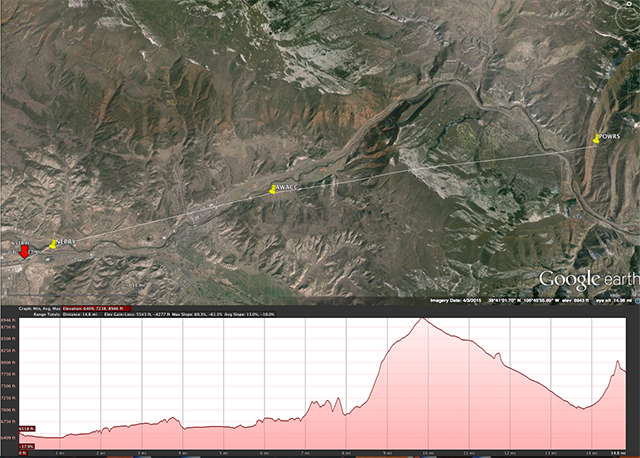
KEGE RNAV(GPS)-D elevation profile, flown as published, from Google Earth, 13 Sep 2015
You can input the relevant points into Google Earth and come up with an elevation profile that shows the magnitude of the problem. As you can see in the chart below map, the highest obstacle comes about a third of the way, shortening your distance to descend. There is a perfectly good valley to the north, why not use it?
A saner approach
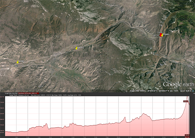
KEGE RNAV(GPS)-D elevation profile, flown along valley, from Google Earth, 13 Sep 2015
By approximating the ground track of the valley you can significantly reduce your obstacle clearance problem. At this point, your descent gradient starts at 12,000' and ends at the runway elevation of 6,547', which is 12.5 as the crow flies but significantly longer via the ground track. The Google Earth chart says "16.1 mi," but it is up to you to specify nautical or statute miles. I've specified nautical, which means our new descent rate is (12,000 - 6,547) / 16.1 = 339' / nm. That is quite a bit more manageable than the straight down the middle requirement.
Conclusion & Lesson Learned
The example approach cannot be flown along course centerline without exercising the EGPWS, scaring the passengers, and completely ignoring stabilized approach criteria. By raising your approach minimums to require a visual sighting of the runway at 12,000', you can fly along the nearby valley and eliminate all the previous concerns.
The lesson learned is this: just because an approach passes TERPS criteria doesn't mean it is safe!
5
Instrument approach math
You don't need an engineering degree to diagram an approach as shown in these examples. If you can plug and chug with a scientific calculator, all you need are some formulas. Here are some handy ones.
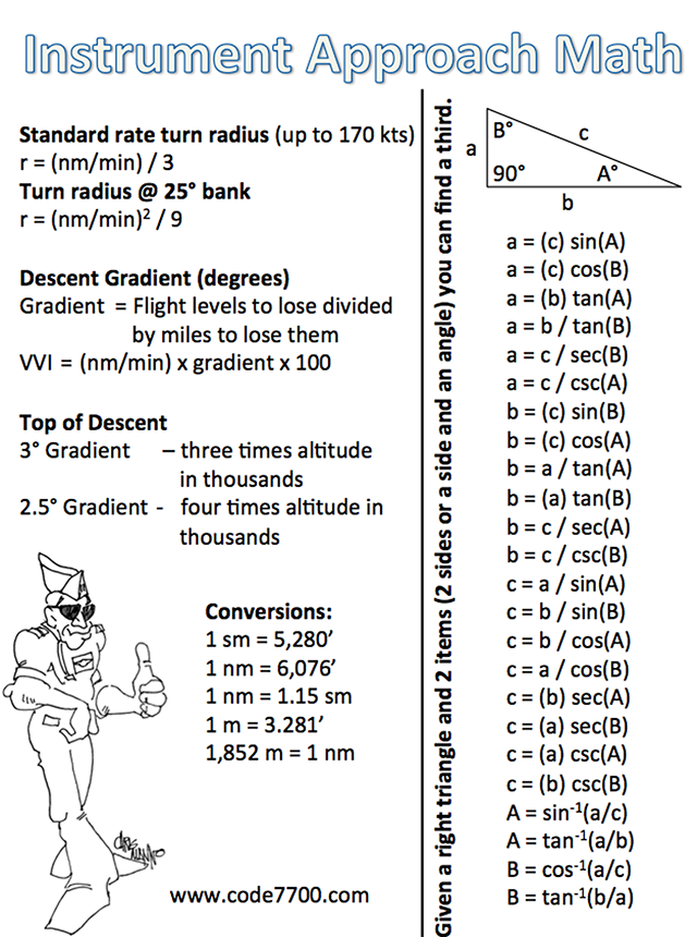
(Click on the figure to download a PDF version.)
References
(Source material)
Jeppesen Airway Manuals
Google Earth