Flying a visual pattern in a jet can seem more art than science to anyone who grew up flying light aircraft and did very little primary training in fast movers. But even for those of us from the military, if we don't practice them often flying an "ideal" visual pattern can quickly become not only an art, but a lost art.
— James Albright

Updated:
2024-03-15
If you apply precise flying techniques to each visual approach you will find that after a while, they do indeed become routine. In that vein, allow me to offer a model of an ideal pattern followed by variations. While every airplane is different, I will use an airplane that flies the base turn at 160 KTAS as an example. I will follow all of that with the math in case you would like to tailor these techniques for something different.
2 — The light wind (15 knots or less) pattern
3 — The severe undershooting wind (more than 15 knots) pattern
4 — The severe overshooting wind (more than 15 knots) pattern
1
The "ideal" pattern
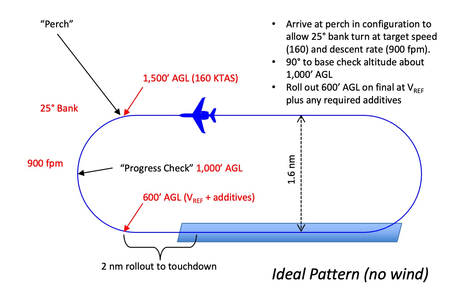
The ideal traffic pattern
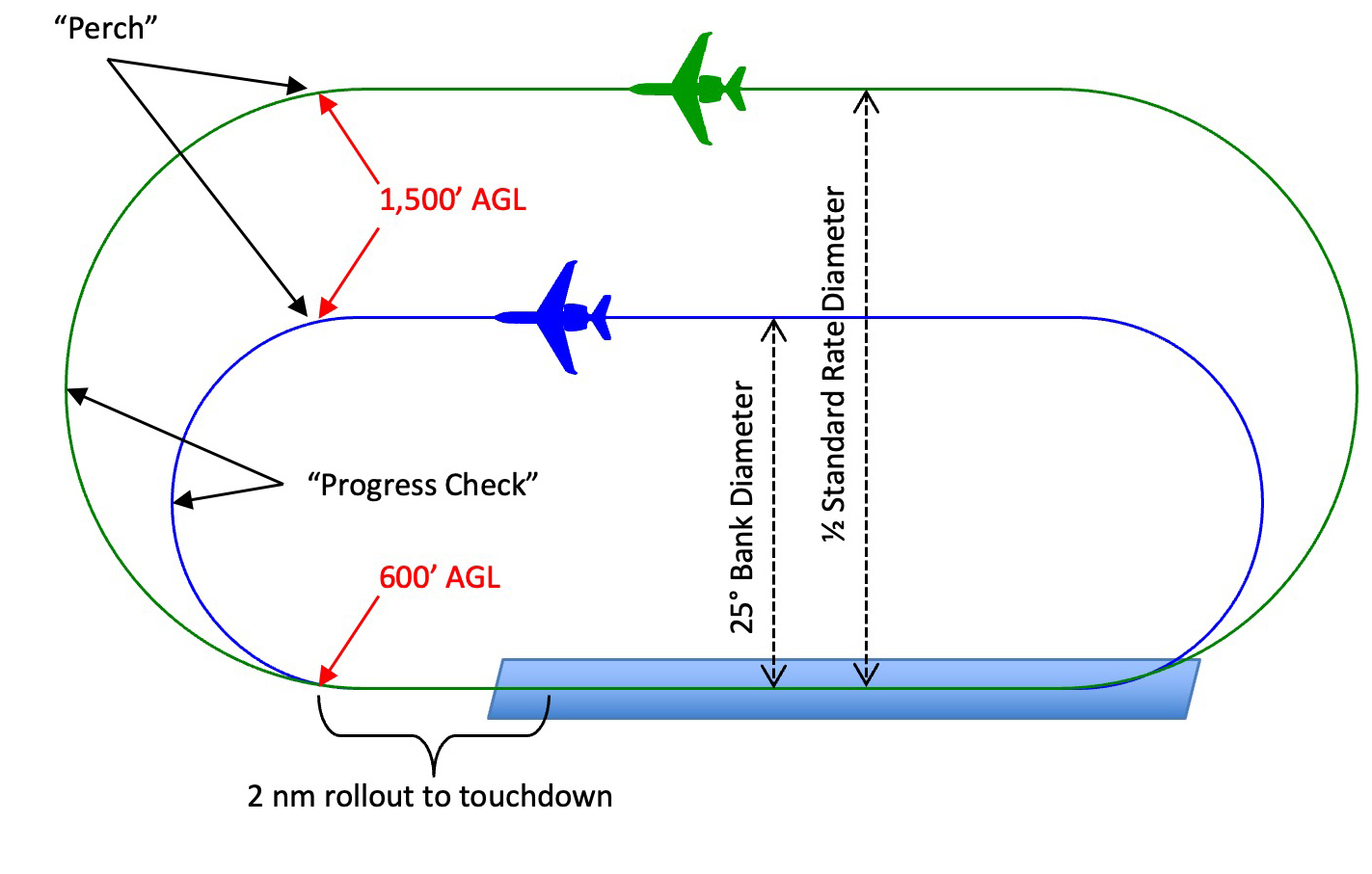
Of course "ideal" is in the eye of the beholder, but given my aircraft's preference for 160 knots starting the base turn and my personal preferences to fly a symmetrical pattern and to roll out precisely on final at 600' AGL and 2 nautical miles, an ideal pattern:
- Starts with a downwind displaced 1.6 nm from the runway at 1,500' AGL.
- Begins the base turn at the "perch," which is abeam your desired 2 nm roll out point.
- Rolls smoothly into a constant 25° of bank and allows the nose to drop into a 900 fpm rate of descent.
- With half the turn completed, half the altitude to lose is lost so the airplane is about 1,000' AGL.
- Rolls out at 600' AGL on an extended centerline, 2 nm from the desired touchdown point, setting up a stabilized approach.
The 1,500' AGL starting point seems to be an international standard for jet aircraft, the 25° of bank is an industry norm for transport category aircraft, and the 2 nm extended final is what is needed to provide a 3° stabilized approach.
But what about those other numbers — 1.6 nm and 900 fpm? They are just mathematical magic, as shown below.
Downwind
It is important to have the aircraft in trim, on altitude, and flying parallel to the runway when on downwind. This will give you the opportunity to establish a level flight power setting and to judge any crosswind drift. But how do you judge drift? The standard method of flying parallel to the runway and looking for the ground track in front of you moving left or right may work in a Cessna 150 but it is not the thing to do in a jet. You shouldn't fixate your gaze for too long at our speeds, especially when you should be busy scanning for traffic. Three better choices:
CL-604 AOM ¶17-20-13
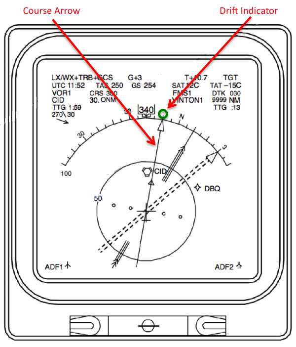
If your avionics provides a drift indicator on your compass card you are all set. Simply place the course arrow on the runway heading or its reciprocal and fly a heading to place the drift indicator on the head (if you dialed in the reciprocal) or tail (if you dialed in the runway heading).
We had a similar set up in our Air Force Boeing 747s and if the other pilot messed this up we would say "kill the drift." Getting into the habit of flying with your desired course under the drift indicator would always kill the drift. I really miss that green donut.
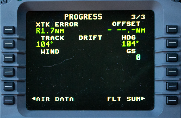
G450 MCDU PROG 3/3
If your avionics system provides a drift reading not accessible through the primary flight displays, knowing how to get the angle with a few key strokes can be very helpful. In the Gulfstream G450/G550 MDCU, for example, pressing PROG and PREV gets you your drift indication.
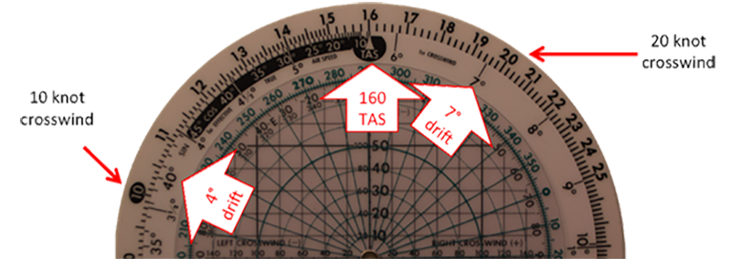
CR-3 wind side at 160 KTAS
Even if you don't have an electronic means of measuring drift, you can compute it with a CR-3 or similar flight computer with a wind side. Using a CR-3, set the TAS index under your expected TAS. (160 KTAS shown.) If you have an electronic readout of the crosswind at altitude, use it. Otherwise, use the tower's reported winds, remembering to consider only the crosswind. On the CR-3, enter the outer scale with the crosswind and read the drift on the inner scale. For example, a 10 knot crosswind at 160 KTAS creates almost 4° of drift. 20 knots creates just over 7° of drift. Photo: , from Eddie's collection. More about this: CR-3 / CPU-26 Exercises.
Perhaps the easiest method would be to remember a few key crosswind drift values for your normal downwind TAS. The correct drift comes to the crosswind divided by your TAS in nautical miles per minute. If you normally fly your downwind at 120 knots (2 nm/min), you would have a 5° drift in 10 knots of crosswind, 10° drift in 20 knots, and so on. At 180 knots TAS (3 nm/min), you would have just over 3° of drift in 10 knots of crosswind, almost 7° of drift with 20 knots of crosswind, and so on
The downwind displacement from the runway depends on the aircraft's turn radius. The turn radius of an airplane flying less than 170 knots is generally the speed, in miles per minute, divided by three. (For example, at 120 KTAS you are flying 2 nm/minute and your turn radius is 2/3 nm.) For our example aircraft flying at 160 KTAS, the turn radius is 0.8 nm so the desired downwind displacement is 1.6 nm. How do we know this? See The Math, below. Of course you may need to adjust for winds. How? See: The Light Wind (15 knots or less) Pattern, below.
The "perch"
We often speak of the point to begin the base turn as described by a 45° line from our touchdown point. This military method of defining the "perch" does not work in a modern environment where we want to have a stabilized final approach no later than 500' AGL. As a technique, we use a 2 nm final approach. The 45° line would work for an airplane with a 2 nm downwind displacement. For our example aircraft, we will have to fly about a half mile beyond the 45° line.
The base turn
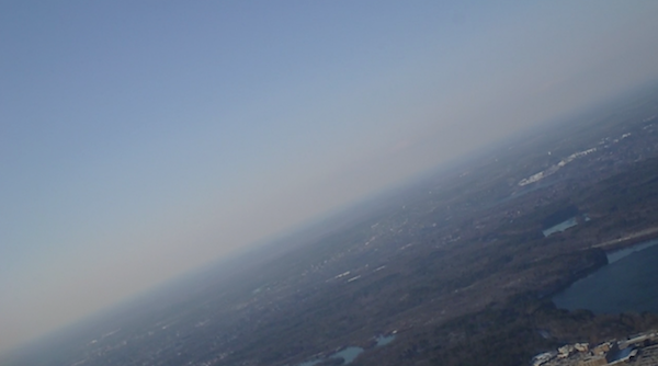
Base turn at Bedford
We should have a precise bank angle in mind, usually 25° but no less than half-standard rate and no more than 30°. Reasons to adjust are given below, starting with The Light Wind Pattern.
We should also have a target descent rate in mind, usually around 900 fpm. How do we know this? See The Math, below. If you have reliable autothrottles setting the target VVI and adjusting as needed is a good place to start. Without autothrottles you need to get back to basics with the Control and Performance Technique. Pull a known quantity of power and wait to see what happens. This can be in terms of EPR, RPM, fuel flow, or even knob-widths of throttle. But give the power reduction a chance to take hold before making follow up adjustments. (Chasing the power fore and aft will only make the other variables worse.)
Rolling Out on Extended Centerline
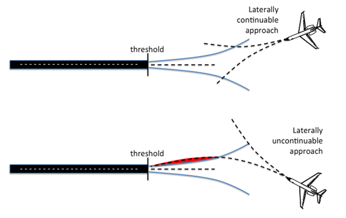
Lateral landing maneuver envelope
There is more art than science when it comes to rolling out precisely on extended centerline. There are many techniques to consider:
- Instrument approach centerlines
- FMS derived centerlines
- The "imaginary rope"
- Synthetic vision
More about each of these techniques: Landing / The Slot - Horizontal.
2
The light wind (15 knots or less) pattern
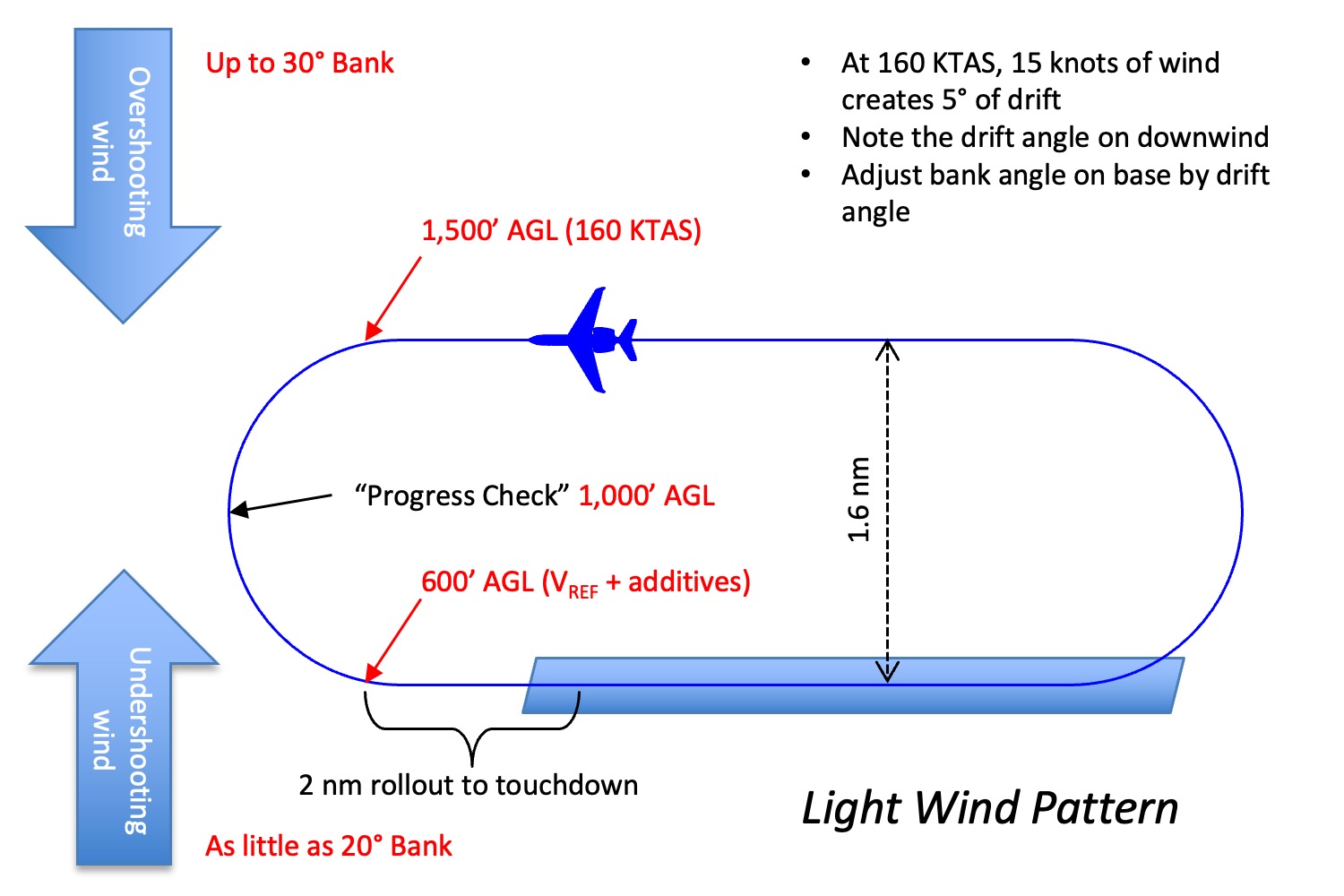
The ideal traffic pattern with "light winds"
We hardly ever find ourselves in ideal conditions and even if we have the pattern to ourselves, we still have to deal with winds. If the winds are 15 knots or less, we can use an old Air Force holding pattern technique to make it all work out.
The technique allows us to roll out on course if we adjust our bank angle by the drift angle prior to the turn. Since our target bank is 25° and we cannot exceed 30° under most circumstances, we will use 5° drift as our limiting correction. When flying at 160 KTAS it takes 15 knots of crosswind to generate 5° of drift so that is the limit of this technique. To adjust:
- Take note of the drift angle on downwind. Your avionics may provide the number for you or you may have to take note of the heading required to maintain a parallel downwind.
- If the wind on downwind is pushing you to the runway, it is an overshooting wind. If you steepen your base turn bank angle by the drift angle, up to 30° of bank, you should roll out on extended centerline.
- If the wind on downwind is pushing you away from the runway, it is an undershooting wind. If you shallow your base turn angle by the drift angle, to as little as 20° of bank, you should roll out on extended centerline.
3
The severe undershooting wind (more than 15 knots) pattern
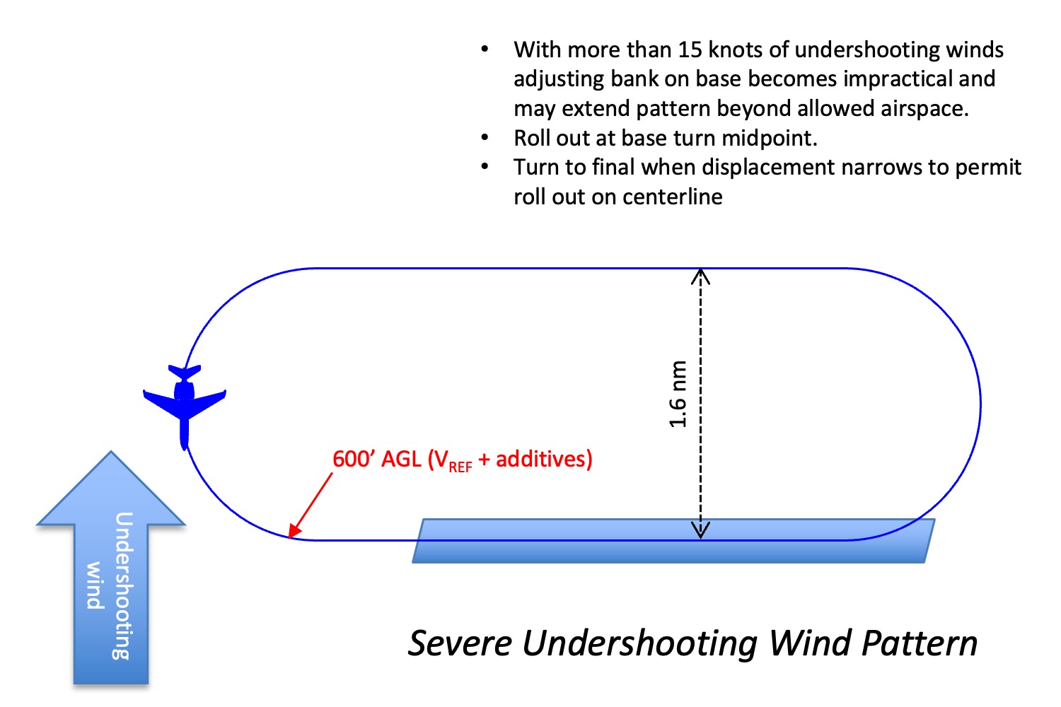
The ideal traffic pattern with "undershooting winds"
If the undershooting winds exceed 15 knots, shallowing our bank angle could extend the pattern outside of protected airspace before the turn is half complete. This will require extra finesse:
- Fly a normally displaced downwind and plan on a 25° bank base turn until the midpoint of the turn. You will need to decrease your normal descent rate since you are flying more air miles and it will take you more time to complete the base turn.
- Once the turn is half completed, roll out on a heading 90° to the runway. You may need to level off.
- Begin your turn to final when a normal 25° bank turn will place you on extended centerline.
4
The severe overshooting wind (more than 15 knots) pattern
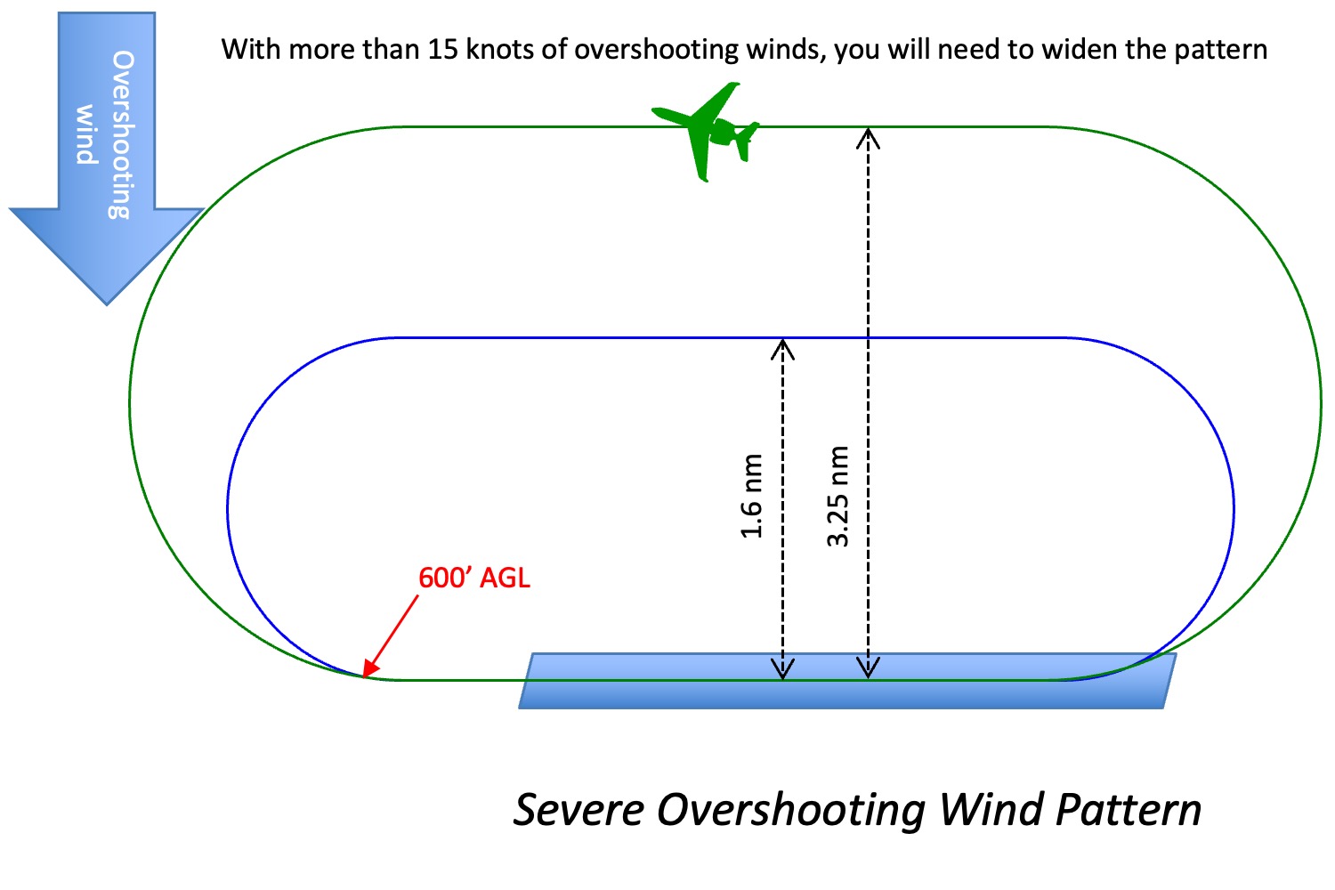
The ideal traffic pattern with "overshooting winds"
If the overshooting winds exceed 15 knots, you cannot steepen your base turn bank angle enough to compensate. You will have to widen your pattern:
- If the winds exceed 15 knots but are still within your landing limits, you might be able to widen the pattern to make the base turn possible at 30° of bank.
- Your best bet may be to widen the pattern as much as allowed to stay within protected airspace, and then play the turn to final to roll out on extended centerline. If the winds are too strong to allow this, you will probably be beyond landing limits.
5
Automation
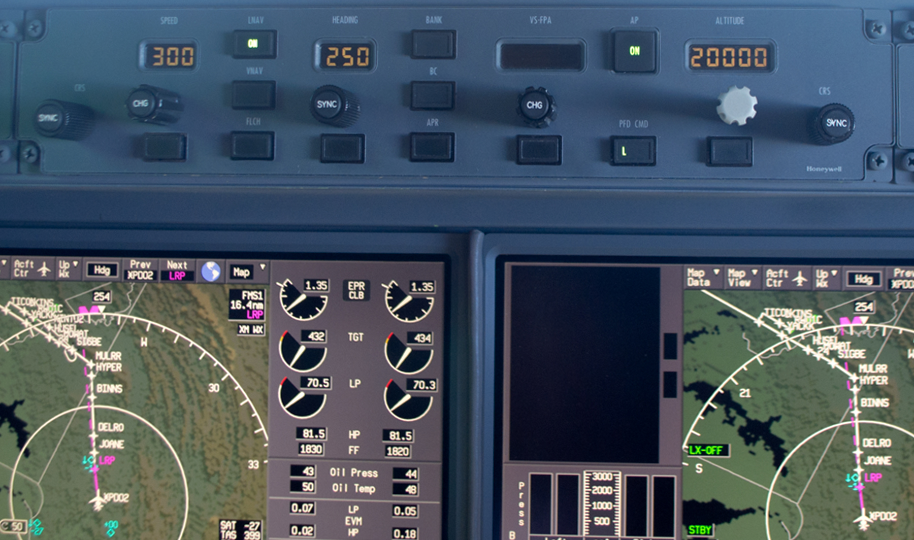
G450 Guidance Panel
There is an on-again/off-again debate about using automation during the approach and landing phase that pits those who think our stick and rudder skills have eroded to the point of endangering safety and those who think we don't spend enough time with our heads out of the cockpit scanning for traffic. I tend to use the automation, especially in a visual traffic pattern where the little airplanes are everywhere. (I don't believe in the Big Sky Theory.) While every pattern is different, here is an example scenario for an "ideal" pattern:
- Use the autopilot to arrive on downwind while scanning for traffic.
- At the perch, configure the airplane as needed for the final turn, select "half bank" if your target bank angle requires it, bring the target altitude to field elevation, and select 900 feet per minute vertical descent.
- At the halfway point, evaluate your progress and adjust the vertical rate and bank angle as necessary.
- Rolling out on final evaluate yourself versus stabilized approach criteria and land the airplane if everything looks good.
6
The math
The traffic pattern "exactly"
I do not advocate flying the visual pattern with a slide rule or calculator dictating every control input, but knowing where the numbers come from gives you a starting position. I've done the numbers for 160 KTAS at 25° of bank and at half-standard rate of turn. That gives me an idea of what will be needed if the situation is somewhere in between.
Turn Radius
The horizontal component of lift will equal the centrifugal force of steady, turning flight. This fact allows development of the following relationships of turning performance:
where:
r = turn radius, ft
V = velocity, knots (TAS)
θ = bank angle, degrees
Source: ATCM 51-3, pg. 178
More about this: Turn Performance.
Rate of Turn
where:
ROT = rate of turn, degrees per second
V = velocity, knots (TAS)
θ = bank angle, degrees
Source: ATCM 51-3, pg. 178
More about this: Turn Performance.
Half Circumference of a Circle
Considering 160 KTAS, 25° Bank
Considering 160 KTAS, Half-Standard Rate Turn
References
(Source material)
Air Training Command Manual 51-3, Aerodynamics for Pilots, 15 November 1963
Gulfstream G450 Aircraft Operating Manual, Revision 35, April 30, 2013.
Please note: Gulfstream Aerospace Corporation has no affiliation or connection whatsoever with this website, and Gulfstream does not review, endorse, or approve any of the content included on the site. As a result, Gulfstream is not responsible or liable for your use of any materials or information obtained from this site.