Back in 1980, when I was a copilot in the KC-135A, computing takeoff performance data meant going through a book of charts and tables and using a very sharp pencil to produce the required numbers. This took about 15 minutes for a novice, but a good copilot could crank them out in about five. I am going through one set of data here just to show how laborious it was. Once the flight was over, the set of takeoff data was checked by a standards and evaluation pilot. Errors of more than 2 knots or 200 feet would require the copilot to be retrained.
— James Albright

Updated:
2015-11-23
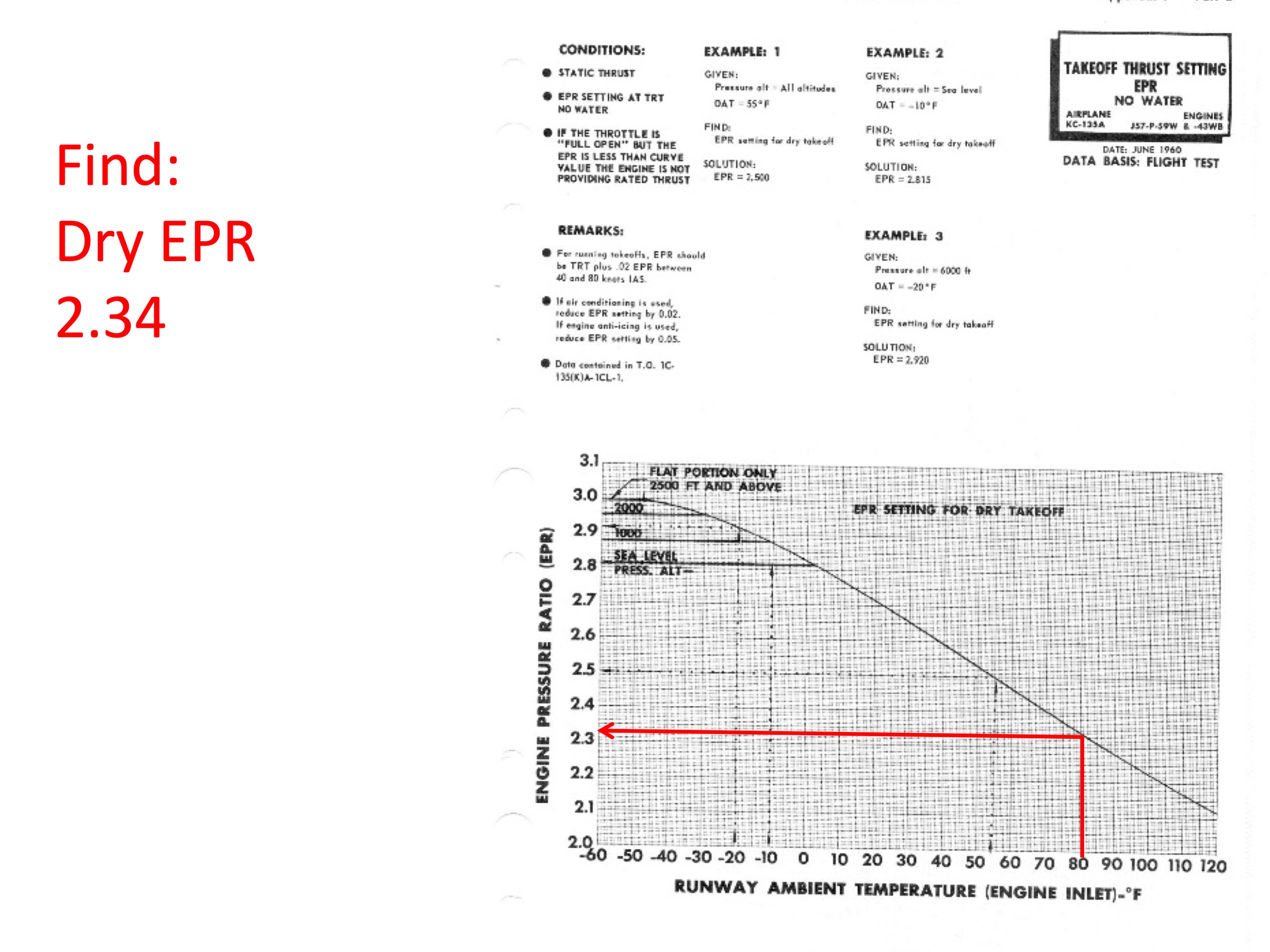
Keep in mind the exercise shown here was an easy one. The runway was dry and there were no obstacles. Furthermore, the objective was to takeoff at maximum weight with water injection augmenting the thrust. There was no "dry" option so only one set of data was needed. For most of our takeoffs using water injection, we would have to compute a set of dry data in case the water injection system failed. (And it often failed.)
KC-135A water injection in action
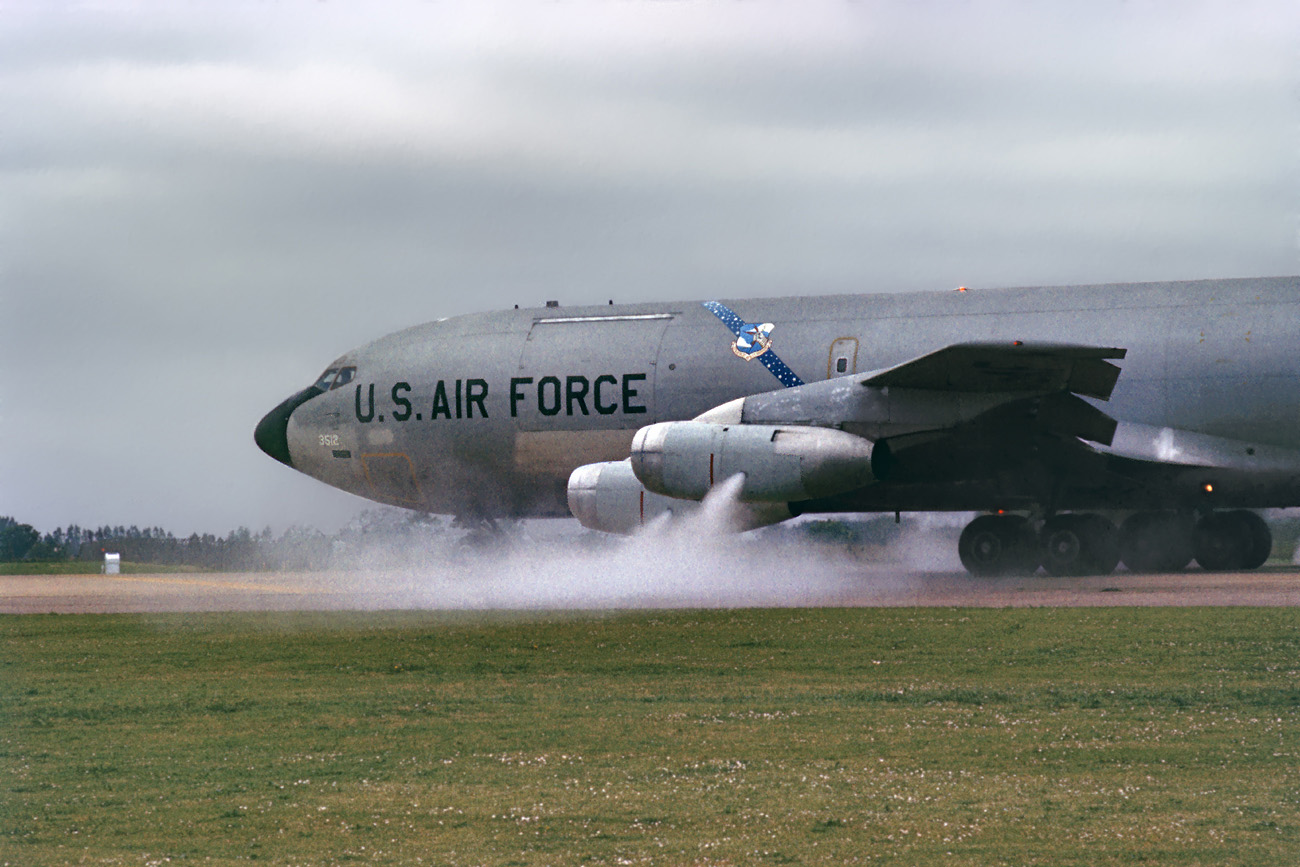
Givens
You normally start with a set of givens, such as the weather, the passenger load, the cargo weight, and the fuel. In the tanker world, you might be given this scenario, where you want to take off with as much as physically possible to maximize the fuel available to offload to the receiver.
Givens
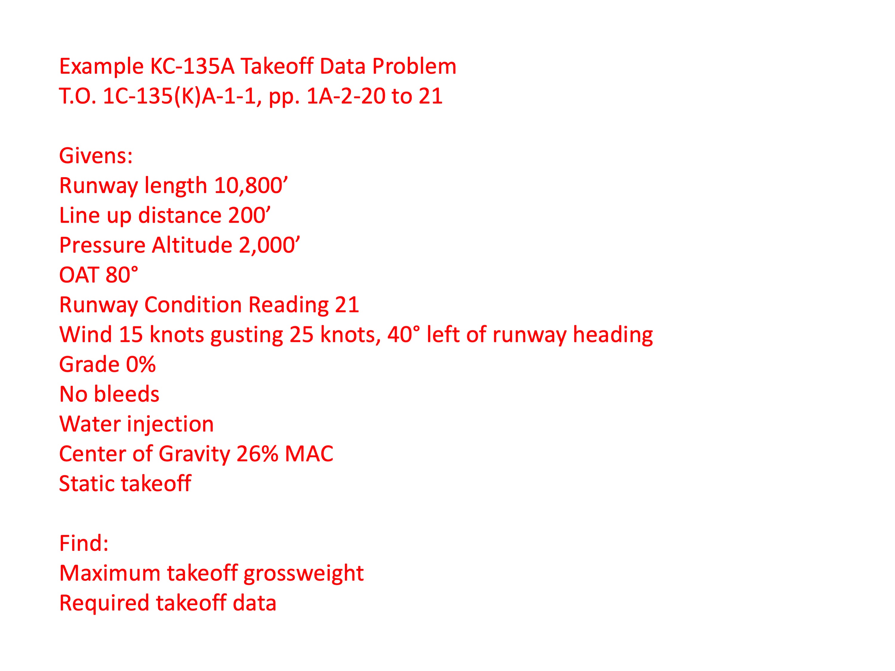
Step 1
Step 1 is to determine the target thrust setting. A "Wet EPR" means this is the Engine Pressure Ratio given the water injection system is operational.
Step 1
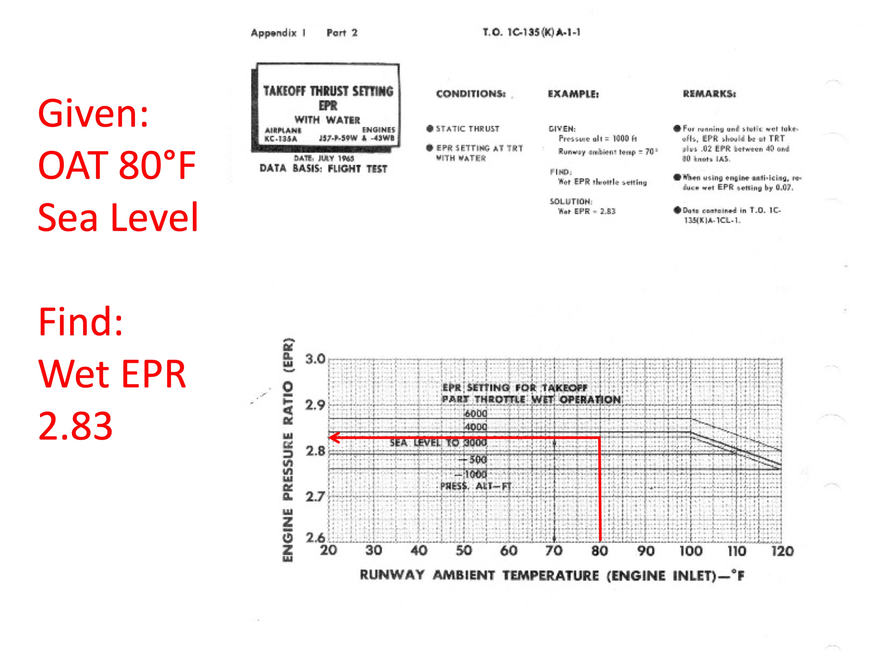
Step 2
Step 2 is to find a "Dry EPR," the thrust setting without water augmentation. In some situations you could delay the takeoff, drain the water, and then go. In this case, we are shooting for maximum gross weight so that isn't an option. But the dry EPR is still needed in case the water system fails after decision speed.
Step 2
Step 3
Step 3 is to compute wind components. The advantage of headwinds are usually not used, but if they are it is without the gust. The crosswind is considered, sometimes with the gust.
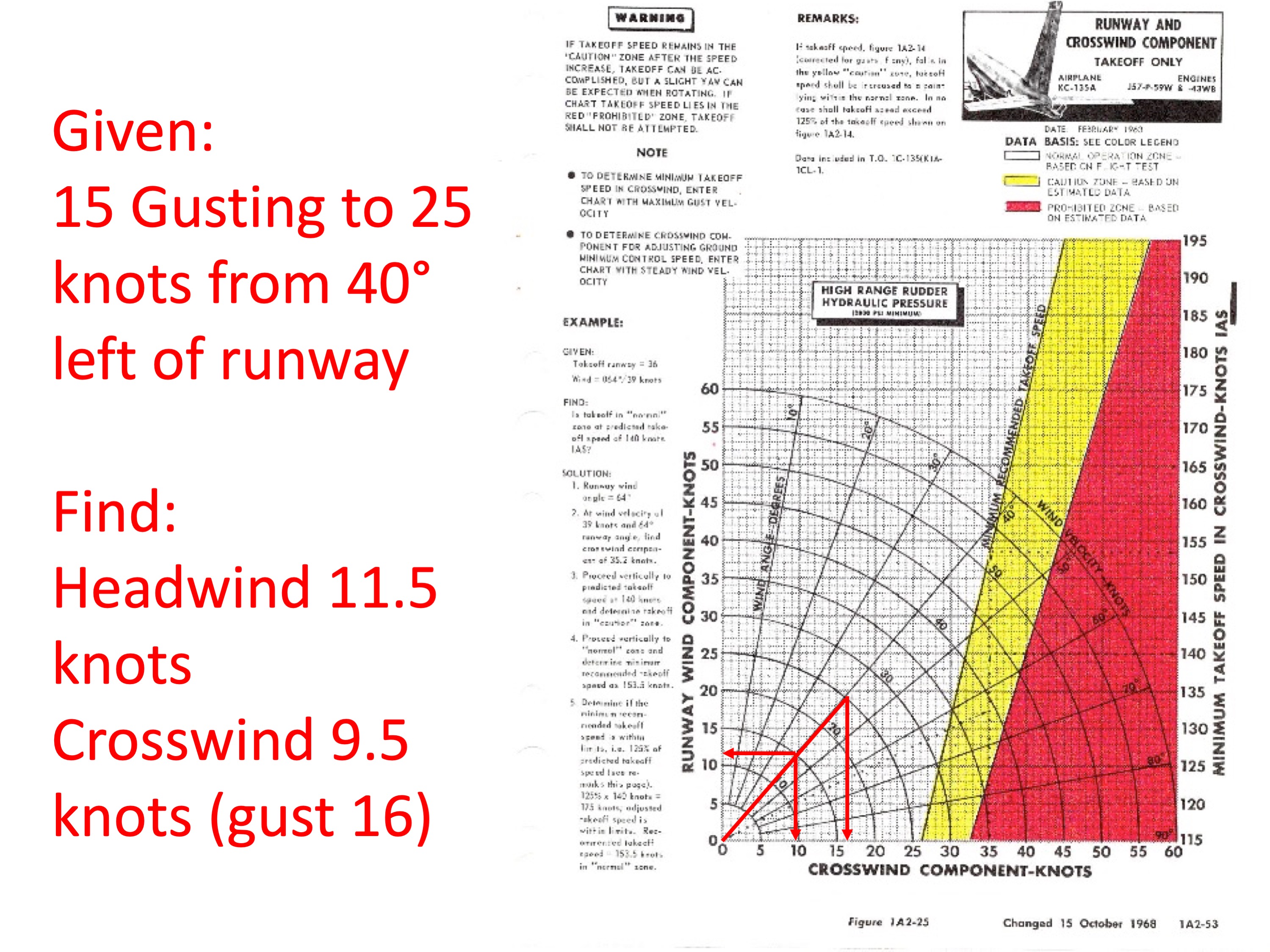
Step 3
Step 4
Step 4 is can be worked to determine a critical field length given the weight, or the weight given the available runway. In this case we determine the longest possible critical field length by subtracting our line up distance from the runway length. This is the first part of this chart and it simply corrects the critical field length with the runway grade, wind, runway condition, engine anti-icing, and bleed condition.
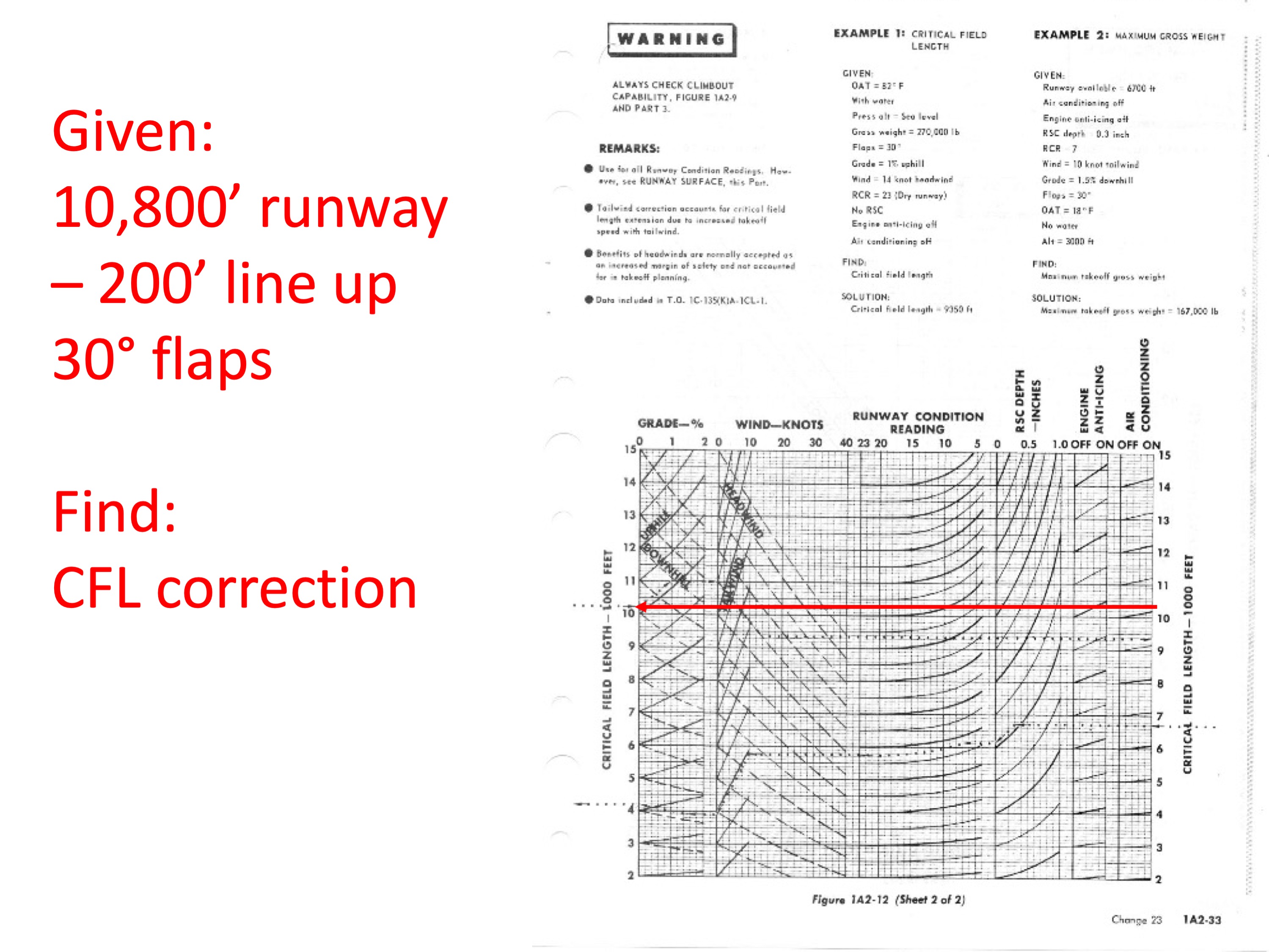
Step 4
Step 5
Step 5 is the second part of determining our maximum gross weight given the runway length. Notice how you are making several turns in the chart where missing by one square can amplify the error so you can get your grossweight 5,000 lbs in error.
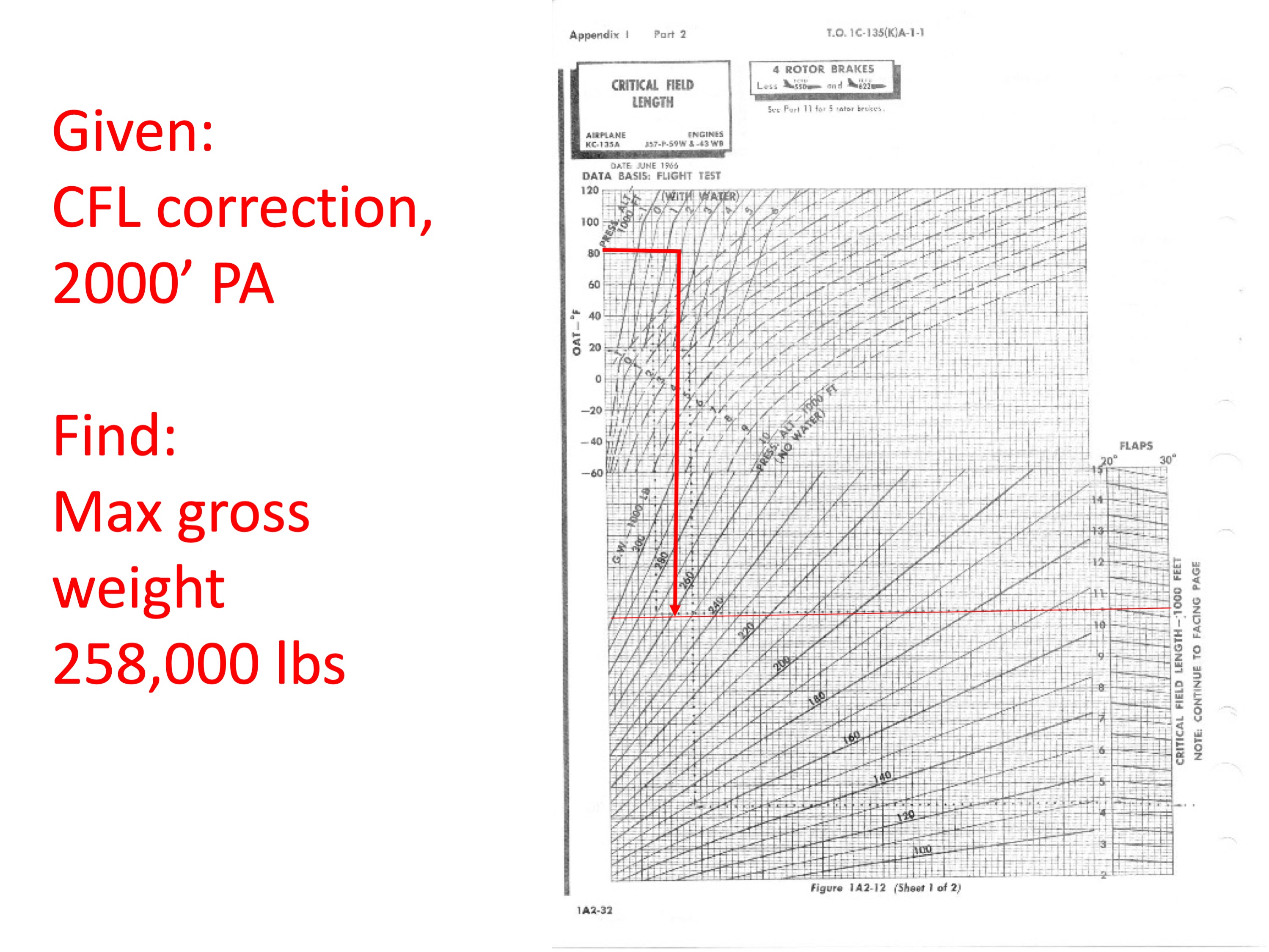
Step 5
Step 6
Step 6 is a check of the climb requirements.
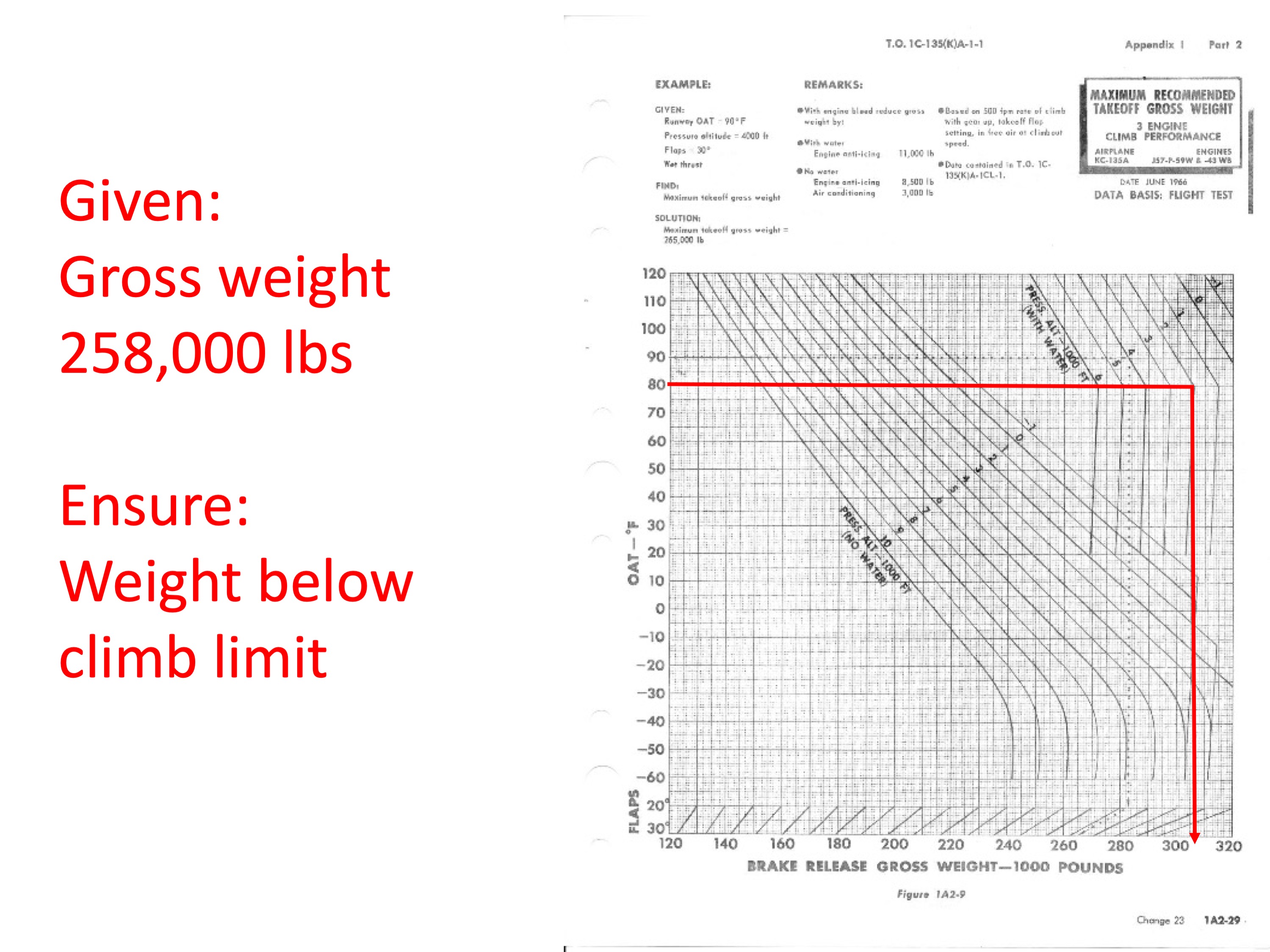
Step 6
Step 7
Step 7 finds takeoff speed.
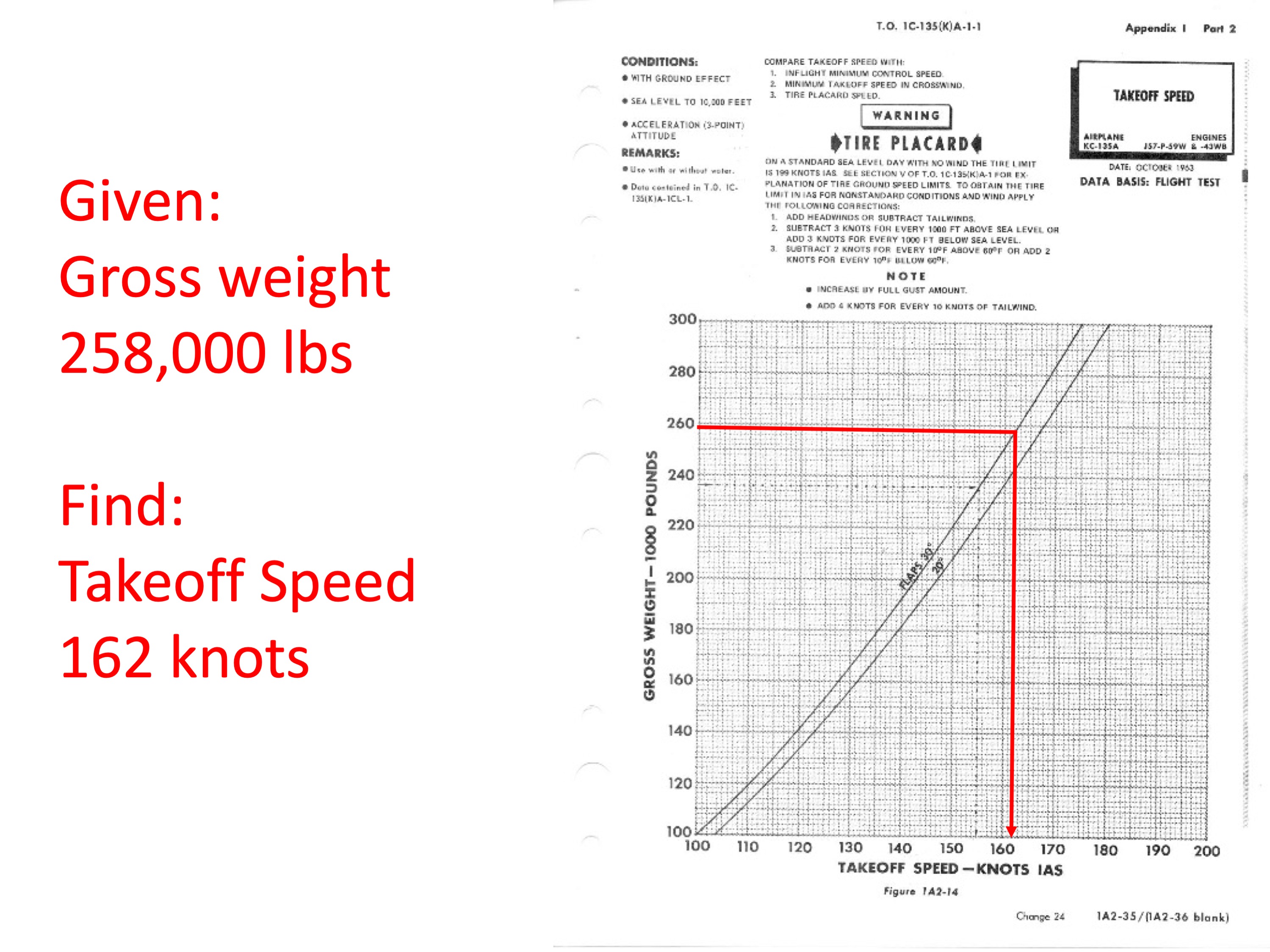
Step 7
Step 8
Step 8 finds inflight minimum control speed.
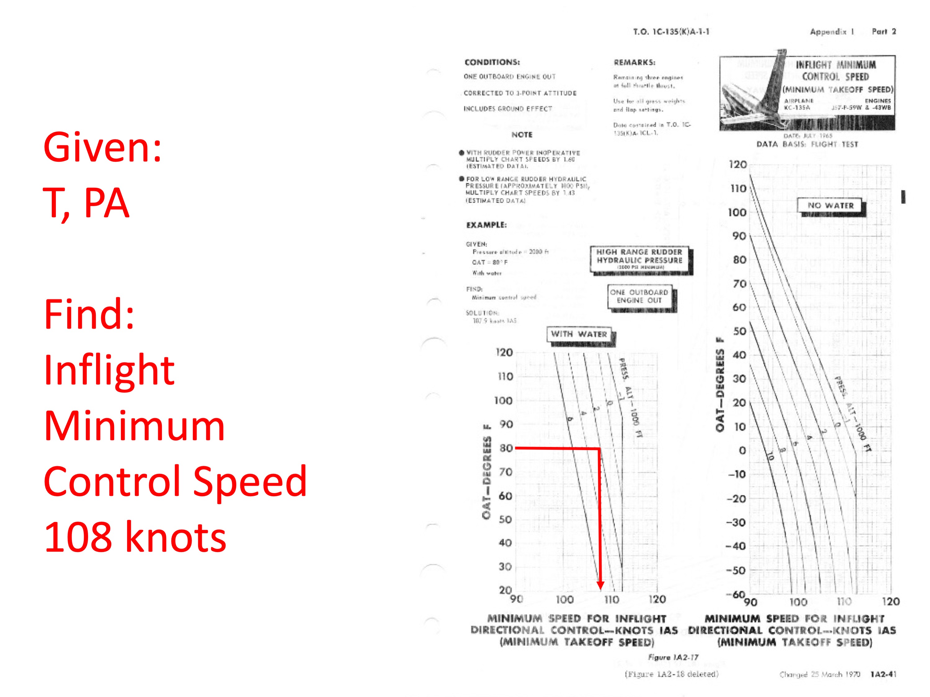
Step 8
Step 9
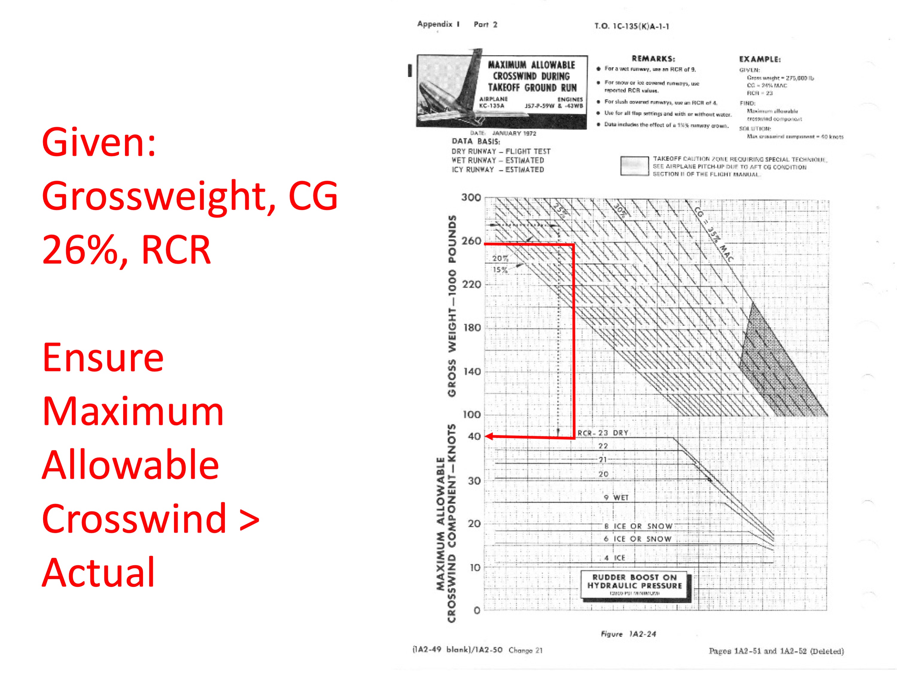
Step 9 ensures the crosswind is less than the maximum allowed.
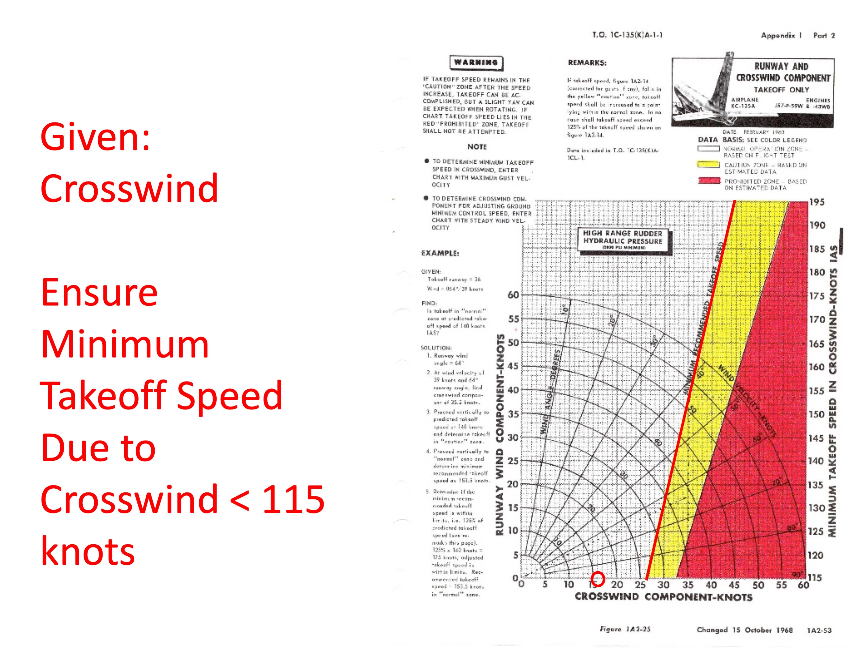
Step 9
Step 10
Step 10 is another crosswind check.
Step 10
Step 11
Step 11 is a check of tire placard speed.
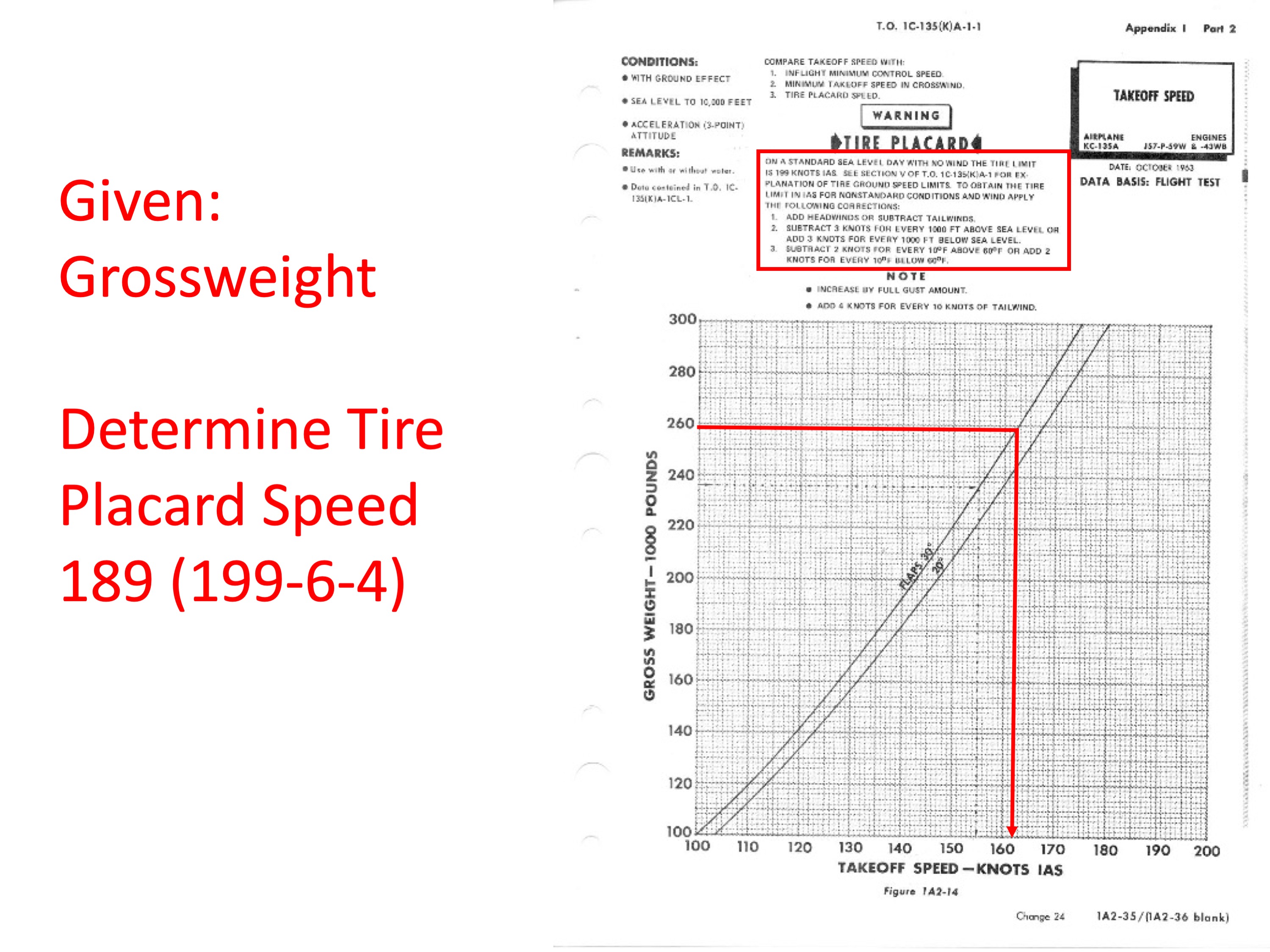
Step 11
Step 12
Step 12 finds ground minimum control speed.
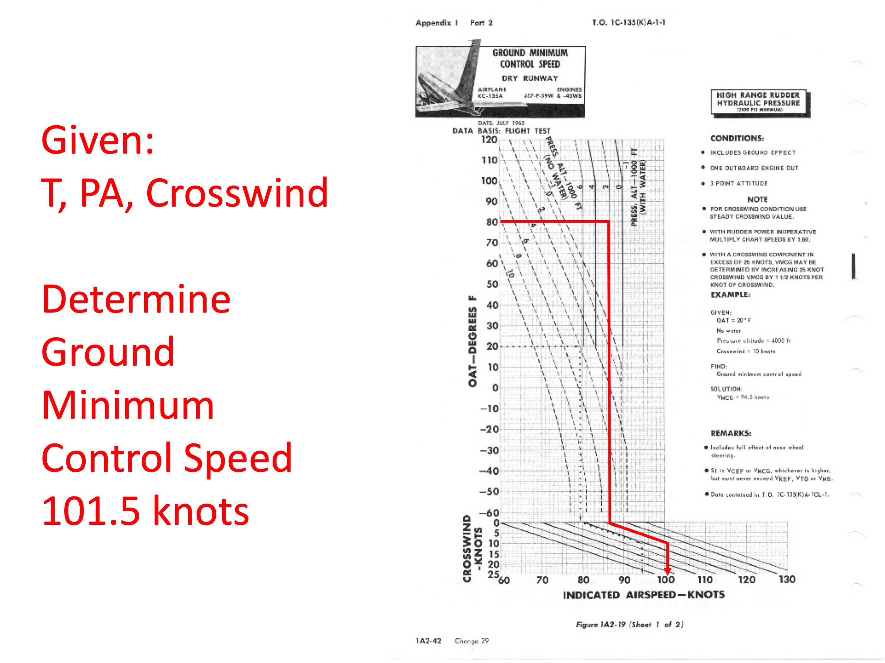
Step 12
Step 13
Step 13 determines a transfer number for the next chart, which finds critical engine failure speed.
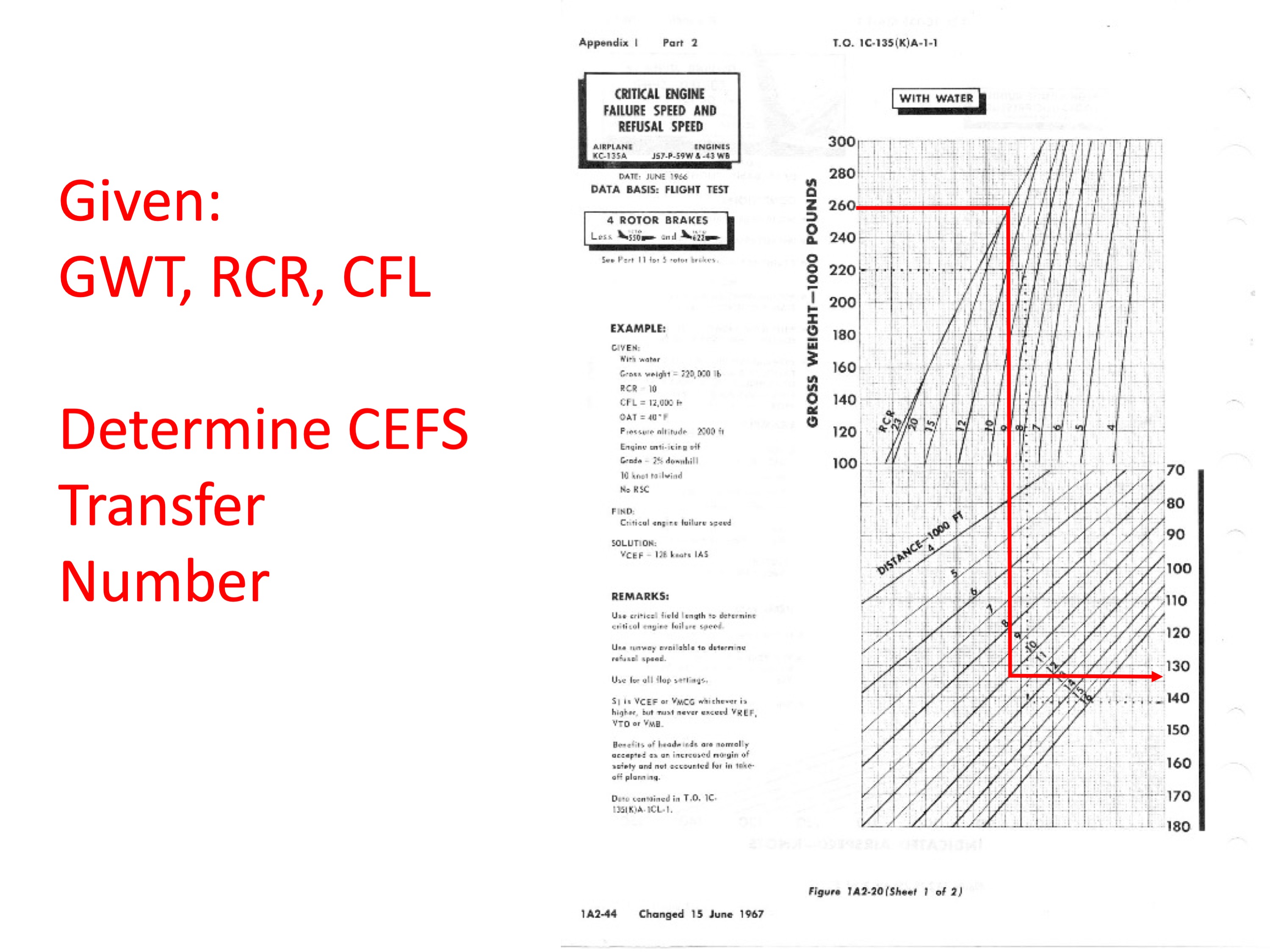
Step 13
Step 14
Step 14 determines critical engine failure speed.
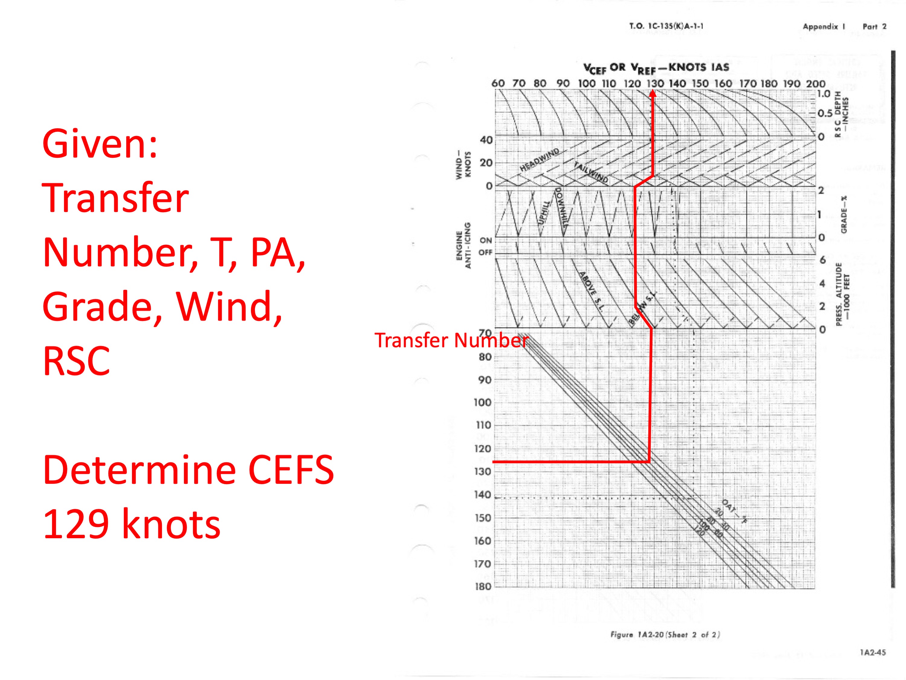
Step 14
Step 15
Step 15 takes every number that can determine decision speed (S1) to come up with it.
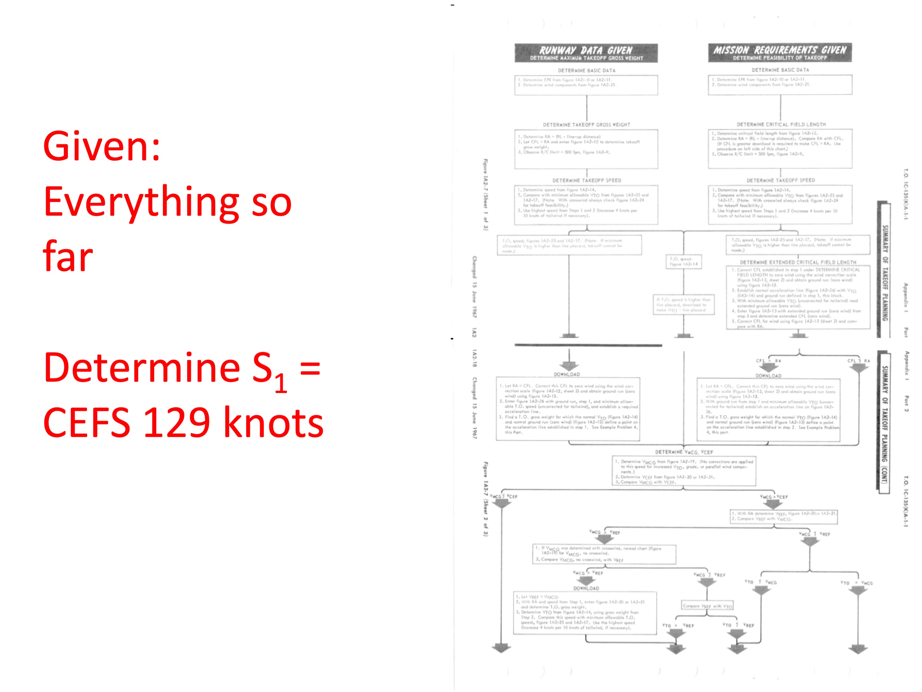
Step 15
Step 16
Step 16 finds maximum braking speed.
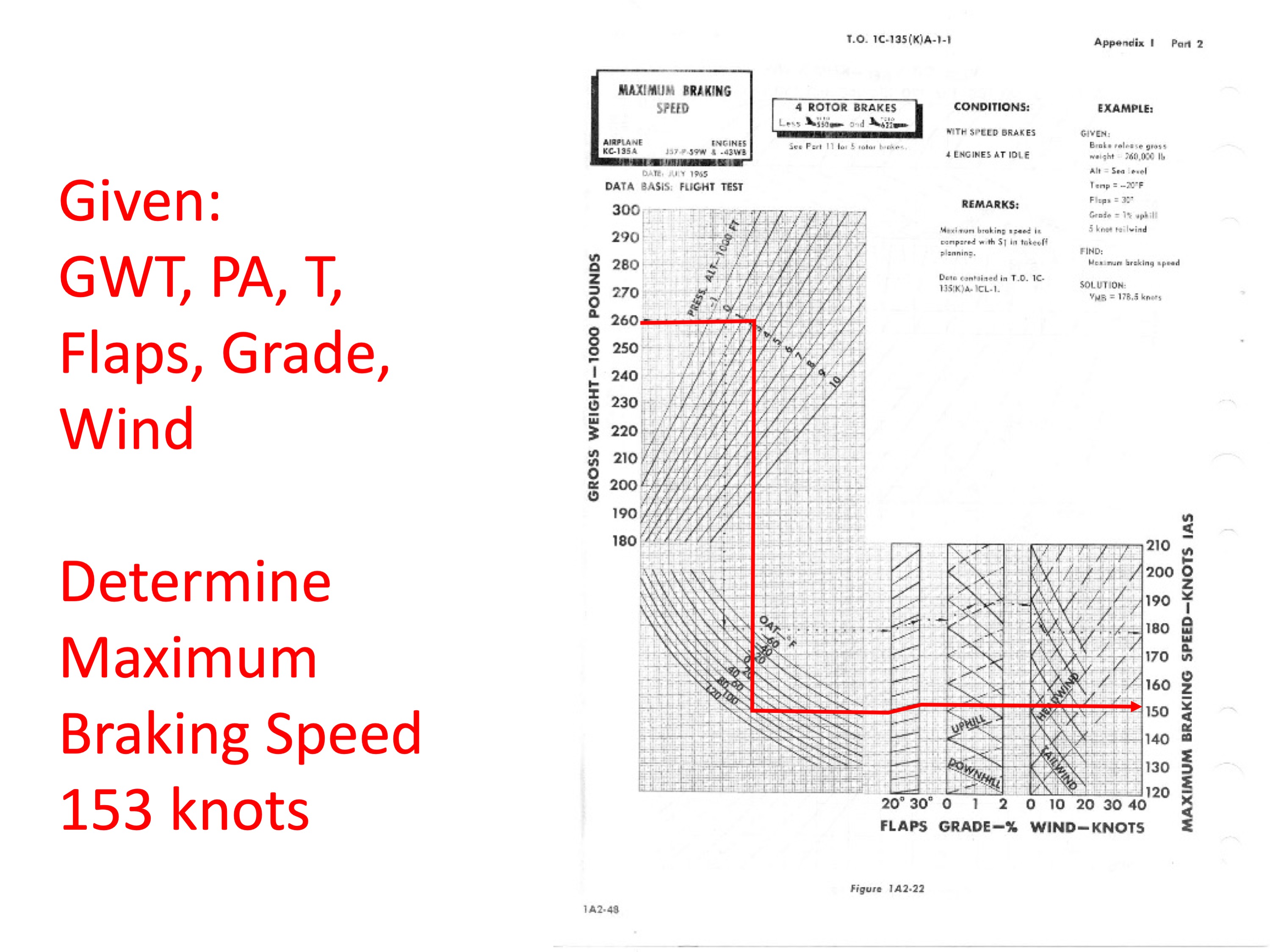
Step 16
Step 17
Step 17 finds rotation speed.
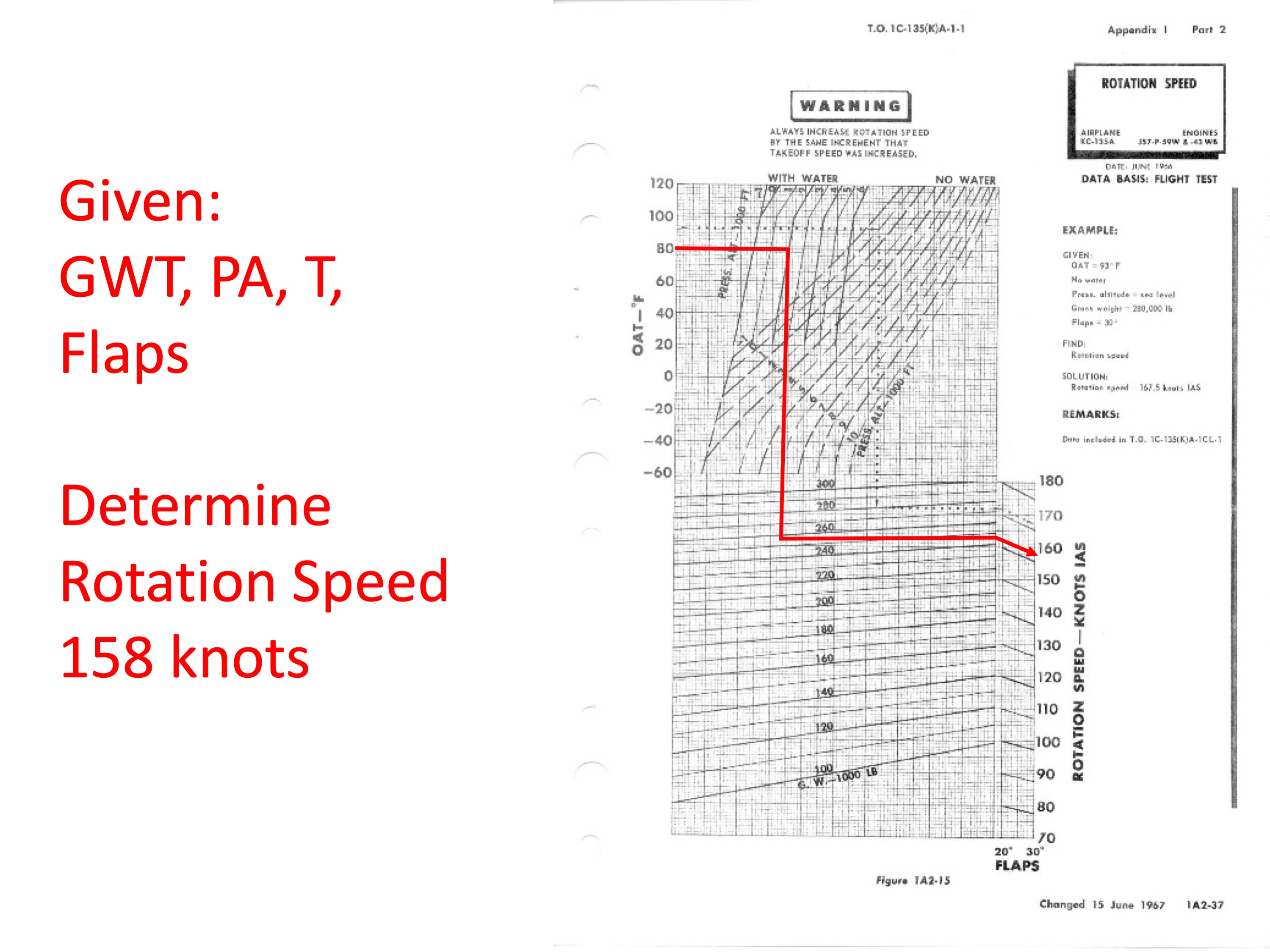
Step 17
Step 18
Step 18 finds the ground run.
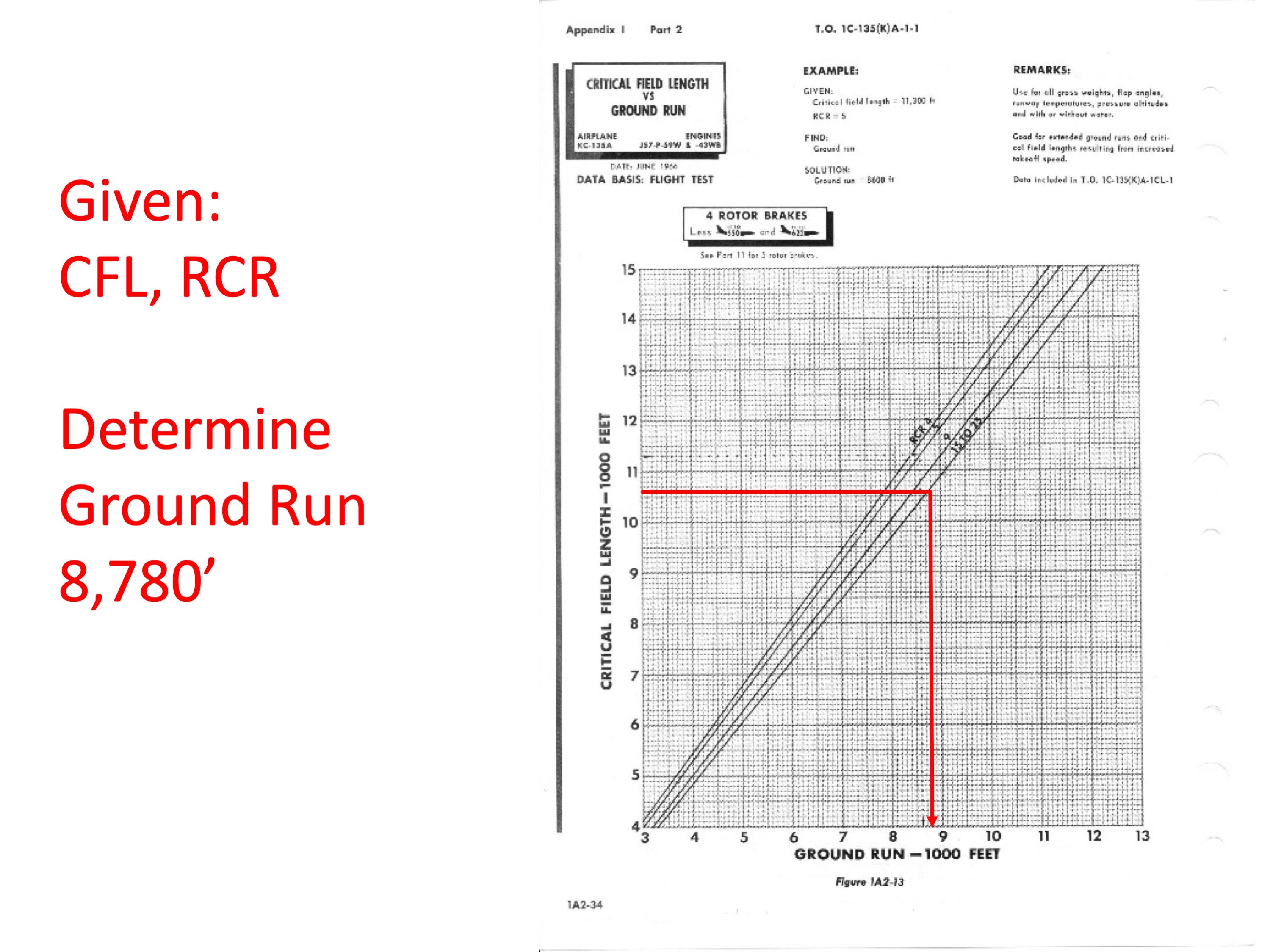
Step 18
Step 19
Step 19 finds the stabilizer trim setting.
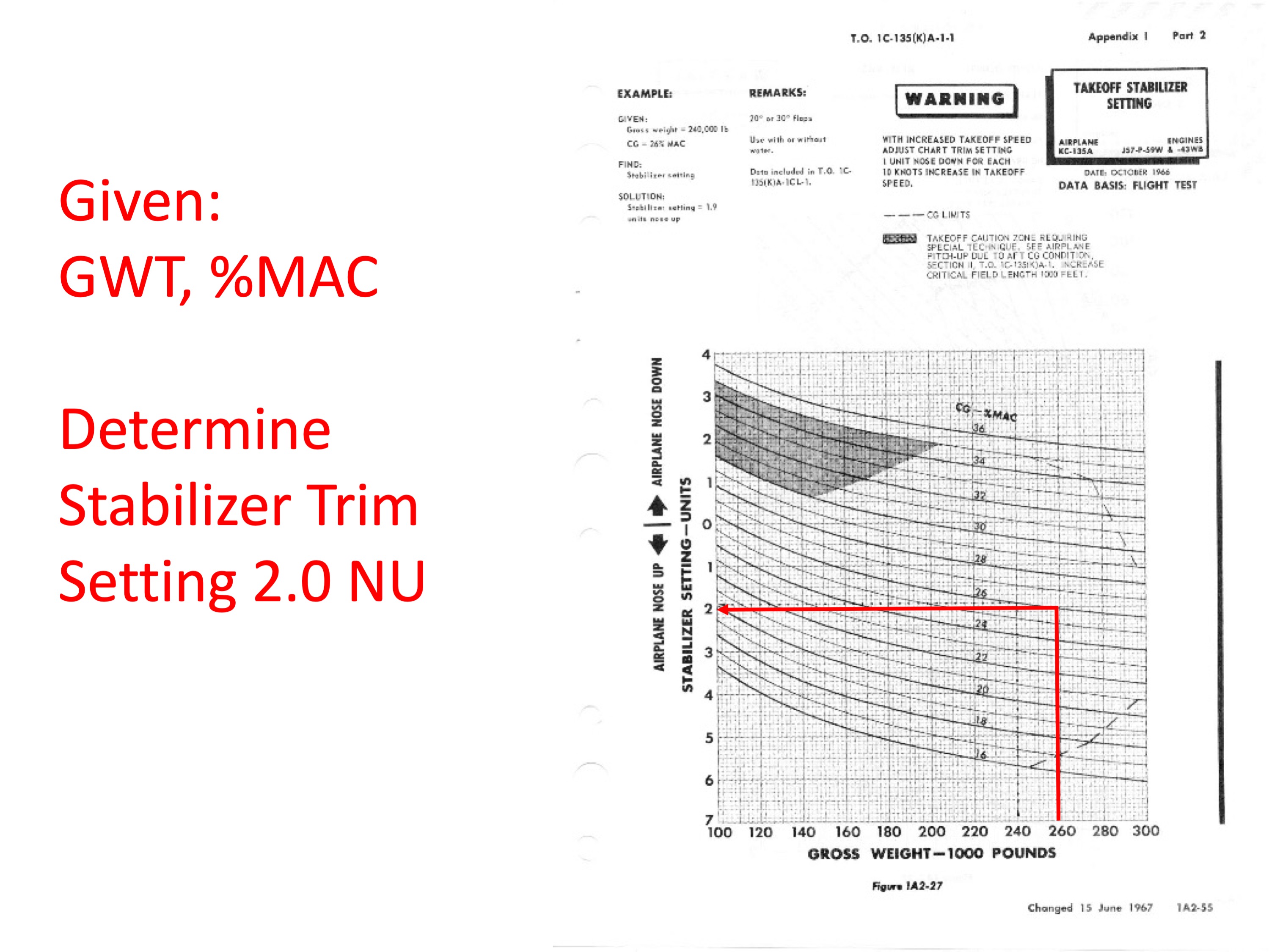
Step 19
Step 20
Step 20 finds the approach speed for an emergency return.
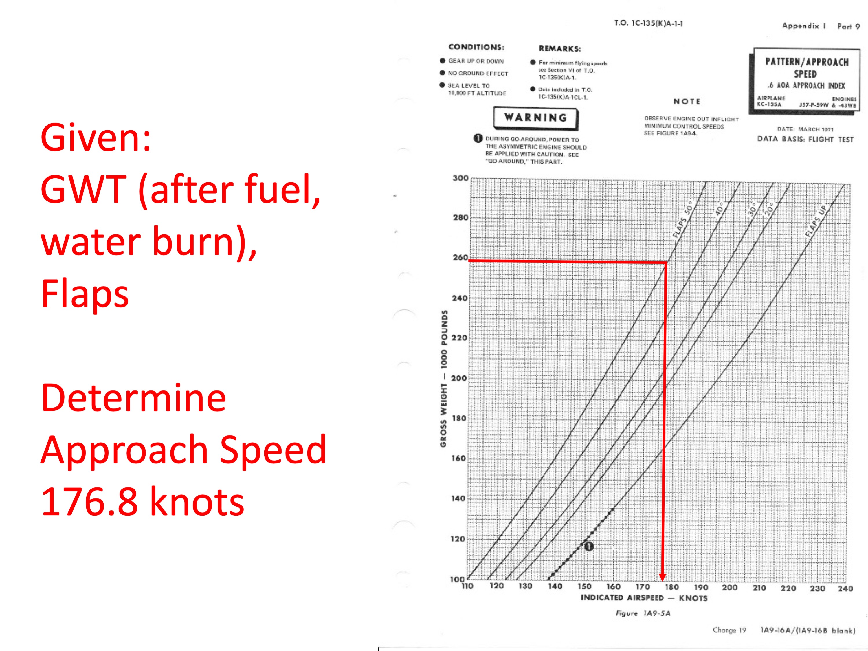
Step 20
Step 21
Step 21 finds the emergency return touchdown speed.
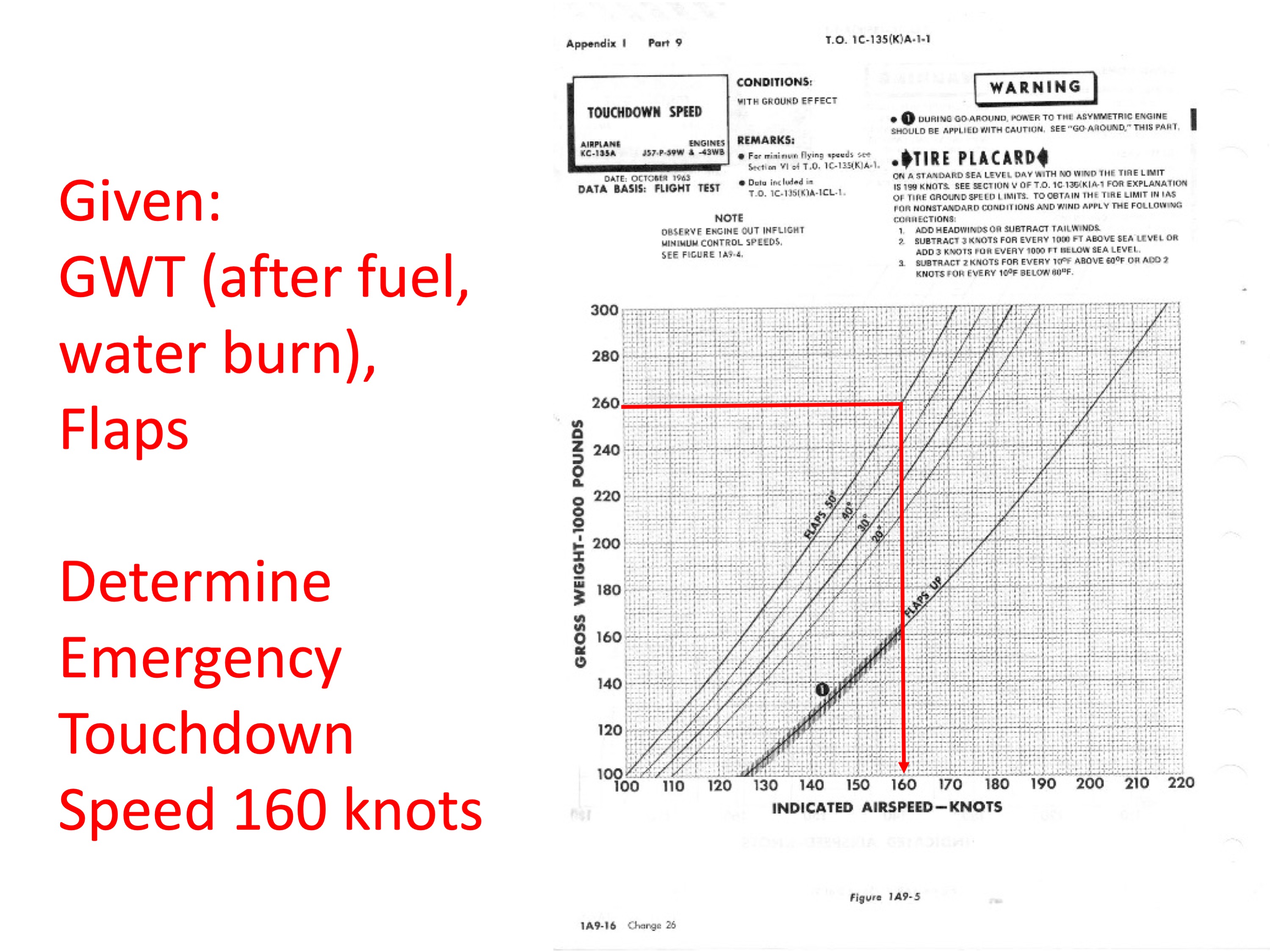
Step 21
Step 22
Step 22 finds EGT limits.
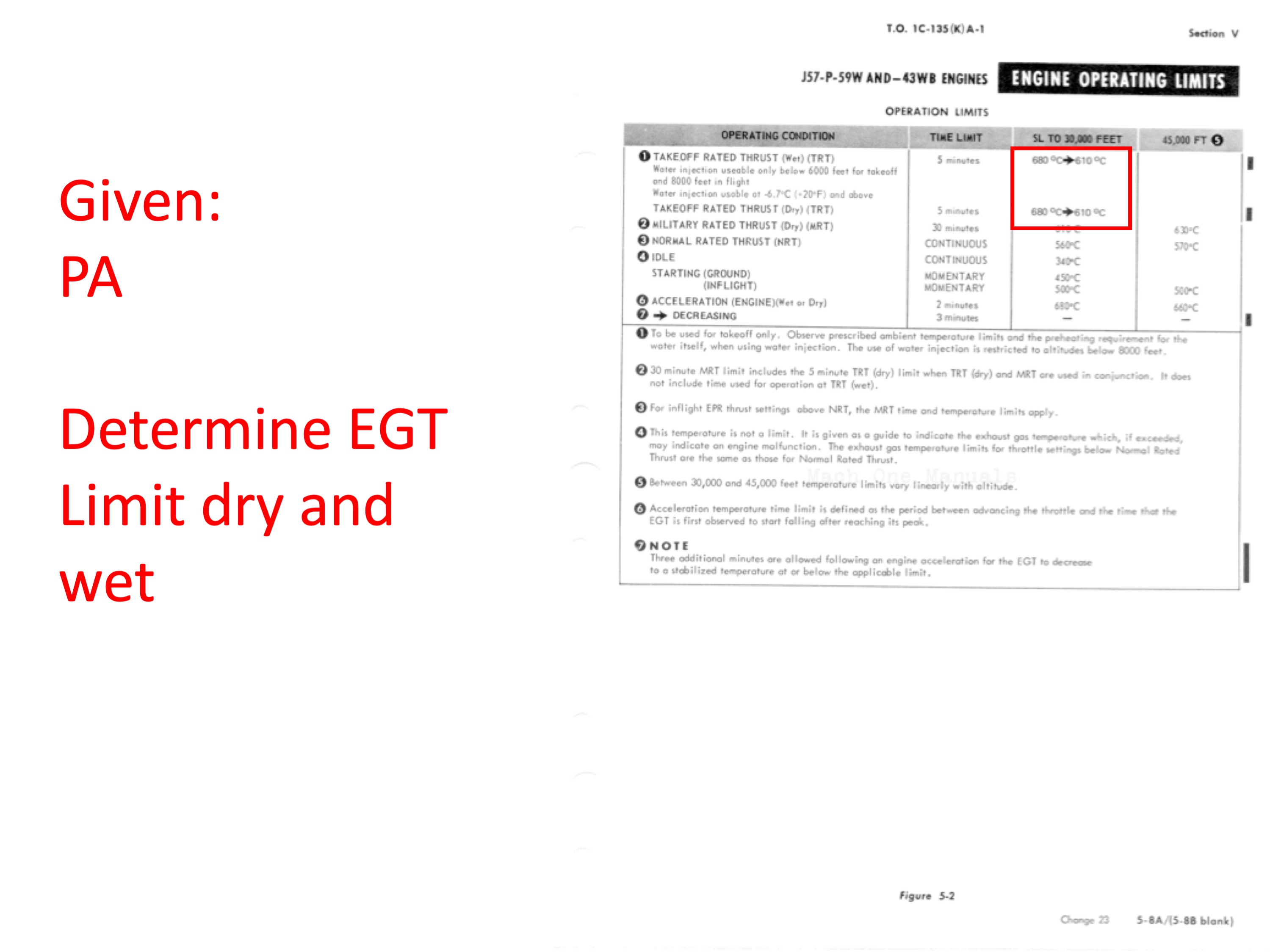
Step 22
TOLD Card
The result of all this is to produce a takeoff and landing data card.
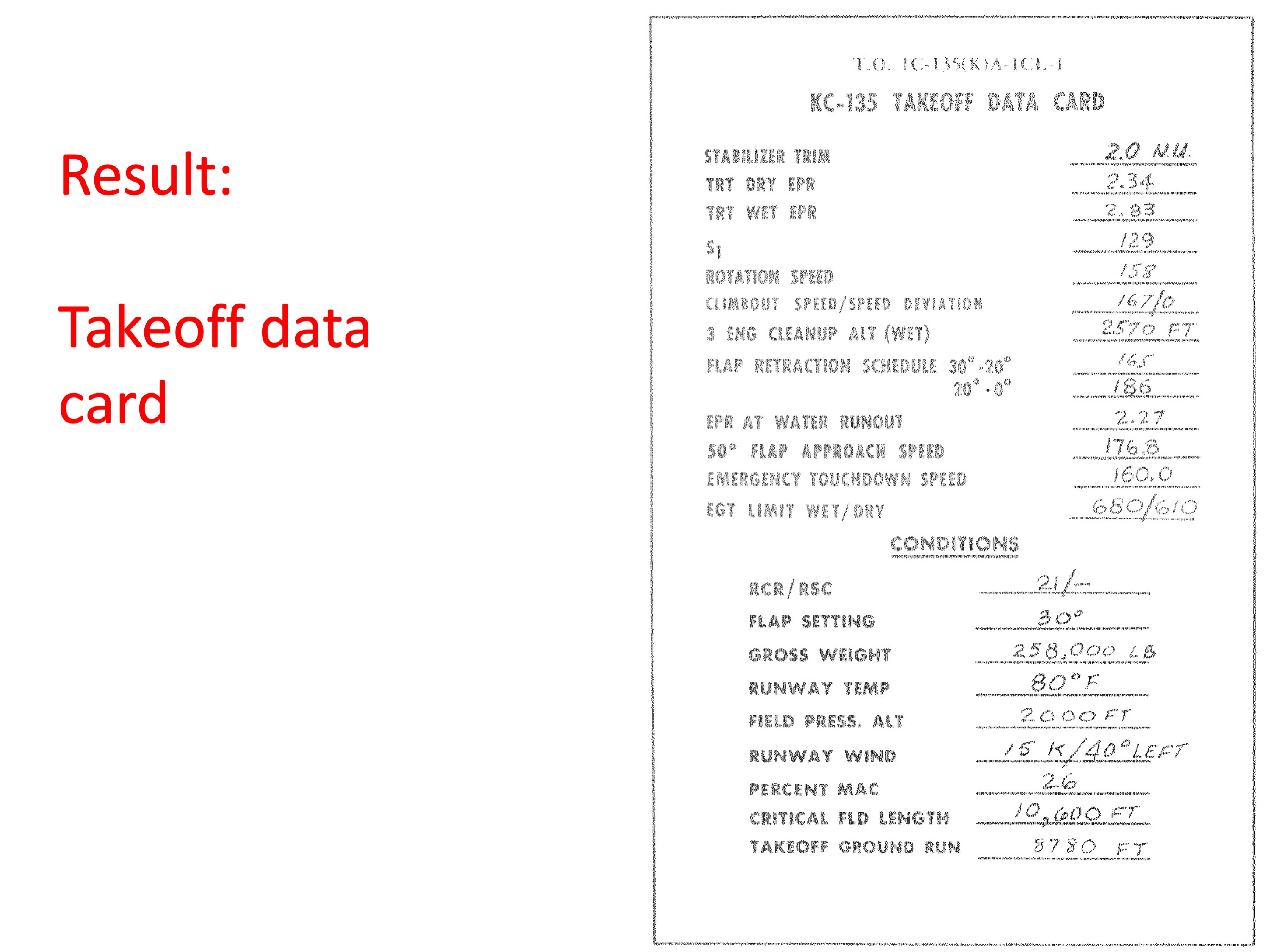
TOLD Card