There are two recurring themes in many mishaps where failures to complete maintenance procedures properly are found causal: the mechanic was fatigued from lack of sleep or extended duty periods, and the procedures for a complicated task were not provided in checklist form. I've seen a few of these first hand in the Air Force where the second problem was addressed by "work cards" but the first problem was ignored due to military priorities. What about us in the civilian world?
— James Albright


1
Accident report
- Date: 7 DEC 2011
- Time: 16:30
- Type: Eurocopter AS350-B2 Helicopter
- Operator: Sundance Helicopters, Inc.
- Registration: N37SH
- Fatalities: 1 of 1 crew, 4 of 4 passengers
- Aircraft Fate: Destroyed
- Phase: En route
- Airport: (Departure) Las Vegas McCarran International Airport, NV (LAS/KLAS), United States of America
- Airport: (Destination) Las Vegas McCarran International Airport, NV (LAS/KLAS), United States of America
2
Narrative
- The accident occurred on the helicopter’s fourth flight of the day. The helicopter was flown on one check flight and two tour flights (one by the check flight pilot and one by the accident pilot) before the accident flight, accumulating about 3.5 hours of flight time with six engine cycles. Neither the accident pilot nor check pilot noted any controllability issues during these flights.
- Radar data obtained from the FAA showed the helicopter following the prescribed Twilight tour route [a standardized nonstop sightseeing tour of the Hoover Dam and the Las Vegas strip an sunset] easterly out of the airport traffic area and then turning to the southeast toward the Hoover Dam. According to the radar data, the helicopter was level at 3,500 feet at a groundspeed of about 120 knots. About 1 minute before impact, radar data showed the helicopter climbing to 4,100 feet, turning about 90° to the left, and then slowing after the turn. The climb and left turn are not part of the Twilight tour flight route. Radar data then showed the helicopter descending to 3,300 feet and tracking a northeasterly course for about 20 seconds, until it entered a left turn and descended at a rate of at least 2,500 feet per minute to impact. The last received radar target was about 1/8 mile from the accident site.
Source: NTSB AAR-13/01, §1.1
- Four mechanics who typically worked together completed maintenance on the helicopter the day before the accident. Of these four mechanics, one replaced the fore/aft servo, one replaced the tail rotor, one replaced the engine, and one conducted a quality control (QC) inspection of the maintenance after it was completed. [ . . . ] In addition, a check pilot, who conducted a post maintenance flight check and a tour flight on the morning of the accident, performed a Before First Flight (BFF) check (an external inspection of the helicopter).
Source: NTSB AAR-13/01, §1.2
The Mechanic
- The mechanic’s training at Sundance Helicopters included indoctrination training, during which he learned records and maintenance procedures and how to read the Eurocopter manuals, and on-the-job training from other Sundance maintenance personnel. He had not attended any helicopter-specific training at the time of the accident. The mechanic estimated that in his 6 months at Sundance, he had completed about six fore/aft servo installations before installing the fore/aft servo on the accident helicopter.
- The mechanic was normally scheduled to work 4 days of 11-hour shifts followed by 3 days off duty and then 3 days of 12-hour shifts followed by 4 days off duty. He stated that he typically reported to work about 1200. He added that he normally went to bed about 0200 and awoke about 1030 and that he maintained approximately the same rest schedule on his days off for consistency.
- The mechanic was scheduled to be off duty December 4, 5, and 6, 2011. On December 4, he awoke between 1200 and 1400. He went to bed between 0000 and 0200 on December 5. On the afternoon of December 5, he was contacted to report to work on December 6. He stated that, therefore, he went to bed about 2200 instead of his normal 0200. He reported that he did not fall asleep until close to 0000, that he awoke about 0500, and that he felt “good” when he awoke. He reported to work about 0550 on December 6 and was assigned the fore/aft servo replacement on the accident helicopter. He stated that he had no difficulty performing the task, that the workload was normal, and that he did not feel rushed. He completed his shift about 1830. See section 3.2.1 for a discussion about the role of the fore/aft servo mechanic’s fatigue in this accident.
Source: NTSB AAR-13/01, §1.2
The Quality Control Inspector
- The mechanic who inspected the preaccident maintenance was designated as a QC inspector for Sundance Helicopters about 6 months before the accident.
- The inspector was also on the 4-days-on, 3-days-off and 3-days-on, 4-days-off schedule and typically reported to work about 1200. He stated that he typically went to bed on his days off about 2200 or 2300 but that he woke up every day about 0730 or 0800.
- The inspector was scheduled to be off duty December 4, 5, and 6, 2011. He went to bed on December 4 about 0000 and awoke about 0800 on December 5. On the afternoon of December 5, he was contacted to report to work on December 6. Therefore, he went to bed about 2100 on December 5. He awoke about 0400 on December 6 and reported to work about 0530. He reported that he did not have trouble sleeping and felt rested. He completed the inspection and ground run of the helicopter about 1800, at the end of a 12-hour shift.
Source: NTSB AAR-13/01, §1.2
The Check Pilot
- The check pilot holds an A&P mechanic certificate, which he received in 2000. The check pilot was hired by Sundance Helicopters in February 2010 as a line pilot. At the time of the accident, he had accumulated about 2,400 total flight hours, including about 1,500 hours in rotorcraft and about 900 hours in airplanes. He worked for 6 years as a helicopter mechanic on Robinson helicopters before joining Sundance as a pilot. He had conducted about 10 to 12 flight checks at Sundance before the accident.
Source: NTSB AAR-13/01, §1.2
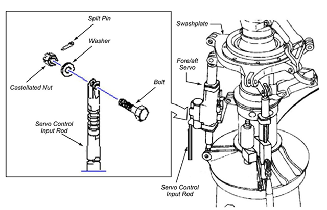
Schematic of the main rotor servo assembly and the fore/aft main rotor servo's input rod assembly, from NTSB AAR-13/01, figure 3.
- The Eurocopter AS350-B2 helicopter is equipped with a single three-blade main rotor system and a two-blade tail rotor for antitorque and heading control. The helicopter is equipped with a mechanical flight control system assisted by a hydraulic tail rotor servo and three hydraulic servos installed on the main rotor: two lateral servos, which transfer the lateral inputs to the nonrotating swashplate (roll), and one fore/aft servo, which transfers the fore and aft inputs to the nonrotating swashplate (pitch). The system is controlled by pilot-actuated control inputs using the cyclic, collective, and antitorque pedals.
- The collective and cyclic inputs are transferred to the helicopter’s main rotor system via control rods interconnected by bellcranks and levers. The control linkages are routed beneath the main cabin and aft to the mixing unit. Pilot movements of the collective and cyclic controls are transferred to the mixing unit, which apportions the commands through the appropriate servo control input rod to a servo input rod assembly.
- Each of the three main rotor servos has three connections: one connection is at the lower end of the servo and is fixed to the main rotor transmission case, another connection is at the upper end of the servo and is secured to the nonrotating swashplate, and the third connection is the servo control input rod that supplies pilot commands to extend or retract the servo. See figure 3 for a schematic of the main rotor servo assembly and the fore/aft main rotor servo’s input rod assembly.
- The servo control input rod is connected to the servo input lever with a bolt, washer, and self-locking castellated (slotted) nut that has a full-circle nylon locking element. The nut is safetied using a split pin (sometimes referred to as a “cotter pin” or “cotter key”), which engages the nut slots and a hole through the bolt threads and prevents the unthreading of the nut. All of the components are made of cadmium-plated steel. In Eurocopter’s certification document, EC 130, “Flight Controls Failure Mode Effects and Criticality Analysis,” Eurocopter indicated that the loss of control of the fore/aft servo would most likely result in a catastrophic failure of the helicopter (a loss of flight control from which a pilot could not recover).
- According to 14 CFR 27.607, any removable fastener whose loss could jeopardize the safe operation of the helicopter must incorporate two separate locking devices. For the Eurocopter AS350-B2 fore/aft servo input rod, the first locking device is the self-locking nut, and the second one is the split pin. In accordance with the Eurocopter Standard Practices Manual, section 1.5.1.2, “JOINING: Assembling by Bolts and Nuts,” the self-locking nut is installed on the bolt and torqued to the minimum specification. The nut is further tightened (up to the maximum specified) until the hole in the bolt threads aligns with a slot on the nut. The split pin is then inserted through the nut and bolt, and the pin’s tangs are bent open 90° or more around the nut.
Source: NTSB AAR-13/01, §1.3
- At the accident site, the fore/aft main rotor servo’s control input rod was found disconnected from the input lever, and the connection hardware (bolt, washer, self-locking nut, and split pin) was not found. The fore/aft servo connection hardware also was not found during subsequent comprehensive and detailed examinations of the wreckage and engine. (The NTSB notes that the main rotor transmission area of the helicopter is not sealed. Therefore, if the connection hardware separates during flight, it most likely would not be contained.) The control input rods for both of the main rotor lateral servos and the tail rotor servo were found properly connected to their respective servo input levers.
- The fore/aft servo’s control input rod was found in two pieces: one piece was an approximate 14-inch section of the upper input rod end that was found disconnected from the fore/aft servo input lever, and the other piece was an approximate 3-inch section of the lower end of the input tube that was found correctly attached to its linkage. Examination of the 14-inch section of the upper input rod end revealed no visible elongation of the bolt hole. The separation points on both sections of the input rod were consistent with overload/impact damage.
Source: NTSB AAR-13/01, §1.4
- The most recent maintenance performed on the accident helicopter was completed on December 6, 2011 (the day before the accident) and included a 100-hour inspection and the replacement of the tail rotor servo, the engine, and the main rotor fore/aft servo with a new (zero hour) unit.
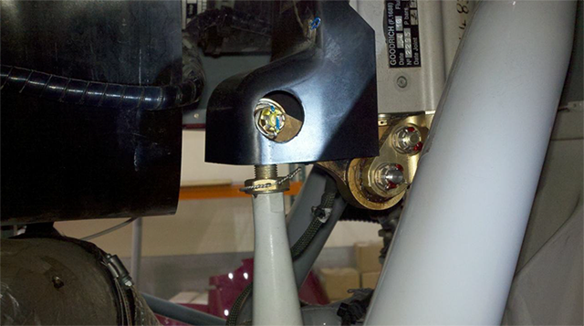
- The fore/aft servo is located just below the main rotor system, and its installation includes an ice shield that is attached to the top of the servo and that has a cutout for viewing the nut and split pin of the input lever connection when the left main gear box (MGB) cowl is opened for access. [See photograph on top of this page] The ice shield was installed on the fore/aft servo and is not required to be removed during installation of the fore/aft servo on the helicopter. However, the shield may be removed to provide more clearance around the input rod connection hardware and reinstalled after the servo is installed.
- According to Eurocopter’s Aircraft Maintenance Manual (AMM), chapter 67, “Rotors Control,” subsection 4-1, “Removal/Installation―Main Rotor Servocontrols” (reference number 67-32-00, 4-1), the following procedures should be followed when installing the fore/aft servo:
- Connect upper ball end of servocontrol to stationary swashplate
- Check that there are spacer bushings
- Offer-up servocontrol, actuator downwards, install [bolt], washers, and nut o Torque the nut
- Safety nut with cotter pin
- Connect lower ball end of servocontrol to MGB flared housing
- Install pin, washer, and nut o Torque the nut
- Safety nut with cotter pin
- Connect input rod to servocontrol distributor
- Install pin, washer, and nut o Torque the nut
- Safety nut with cotter pin
Source: NTSB AAR-13/01, §1.5
- Eurocopter does not require that the nut be replaced when the bolt is replaced, unless the nut does not meet the torque limits. In addition, Advisory Circular (AC)43.13-1B, “Acceptable Methods, Techniques, and Practices―Aircraft Inspection and Repair,” section 7-64, “Self-Locking Nuts,” states, “After the nut has been tightened, make sure the bolt or stud has at least one thread showing past the nut. DO NOT reuse a fiber or nylon lock nut if the nut cannot meet the minimum prevailing torque values.”
- During postaccident interviews, the mechanic indicated that when determining whether a nut can be reused, he removes it, cleans it, and then inspects it for any cracks, damage, or discoloration. The mechanic indicated that he then threads the nut on the bolt to see if it will thread all the way down, and if he is able to turn the nut down to where the shank is visible, he replaces the nut. In the case of the accident helicopter, he deemed the hardware airworthy.
- When asked when or if hardware could be reused, the inspector responded that the Eurocopter Standard Practices Manual provides guidance on when the hardware can be reused. He reported that based on his personal experience, if the nut can be threaded all the way on by hand, it cannot be reused because it has lost its entire locking feature.
- [ . . .] at the time of the accident, Sundance required mechanics to complete a parts form to request new hardware. However, no such form was completed, and the mechanic indicated that the hardware was reused.
Source: NTSB AAR-13/01, §1.5
3
Analysis
Duty time limits
Back in 1996 when ValuJet Flight 592 crashed into the Everglades the cause was determined to be over 100 expired chemical oxygen generators that should not have been carried in the first place. Part of the blame was placed on an inspector who had been on duty for an extended period. The NTSB recommended the FAA establish duty time limitations for maintenance personnel as a result. Here we are 20 years later and nothing has been done about this.
This helicopter appears to have lost control because of an improperly reused part and another missing part. Both the mechanic and inspector were suffering from the fatigue related to changing from night to day shifts and the lack of recent sleep. They were operating under 14 CFR 135 where there still remains no duty time limitations for mechanics.
The NTSB has added to their recommendations in a statement that bears copying: "Establish duty-time regulations for maintenance personnel working under 14 Code of Federal Regulations Parts 121, 135, 145, and 91 Subpart K that take into consideration factors such as start time, workload, shift changes, circadian rhythms, adequate rest time, and other factors shown by recent research, scientific evidence, and current industry experience to affect maintenance crew alertness." (NTSB AAR-13/01, §5.1)
Work Cards
A common practice for aircraft mechanics in many organziations is to study a loosely worded description of the task to be undertaken and then head to the hangar floor to accomplish the task. Once completed, an inspector (who could be the very same mechanic), checks the work using his memory of the task. This is a recipe for error.
This may have been a factor is this mishap. The NTSB recommendation is another item to cut and paste into a company operations manual: "Using work cards that clearly delineate the steps to be performed and critical areas to be inspected to support both the maintenance and inspection tasks is one way to mitigate inadvertent errors of omission in the performance and verification of maintenance tasks, especially tasks involving critical flight controls." (NTSB AAR-13/01, §5.1)
- The NTSB evaluated the most likely scenarios for why the helicopter experienced a loss of control during the accident flight: (1) jamming or obstructions in any of the servos, (2) hydraulic system failure, (3) other system failures (a failure not involving the fore/aft servo connection hardware) that could have resulted in the same flight profile, or (4) the disengagement of the fore/aft servo bolt in flight.
- The four servos were sent to the Meggitt Control Systems facility in Coventry, United Kingdom, for detailed examination by Meggitt personnel under NTSB supervision. An initial inspection revealed that all four servos were severely damaged by impact forces and, therefore, could not be functionally tested. The four servos were torn down and examined, and the examinations did not reveal any indications of a failure condition (jamming or obstructions in any of the servos) that would have affected the operation of the servo. Further, a review of the helicopter maintenance log revealed no indications of problems on any of the four servos.
- No evidence was found indicating that a preimpact loss of hydraulic pressure occurred. A loss of hydraulic pressure is indicated to the pilot by a red HYD alert light and an audible tone. If this occurs, the flight controls can be operated manually. [ . . . ] if a loss of hydraulic pressure had occurred, the expected response would be to maintain straight and level flight and to decrease airspeed; however, the radar data showed the helicopter climbing, followed by a sharp left turn. Although the radar data show the helicopter slowing after the left turn, the data are not sufficient to determine if the decrease in groundspeed was the pilot’s response to a loss of hydraulic pressure or as a result of the climb.
- Although Eurocopter stated that some other disconnection in the mechanical flight control system could have potentially resulted in the same radar track, no preimpact disconnects were identified in the flight control system during the on-site examination other than the fore/aft main rotor servo control input.
- Microscopic examinations of the fore/aft servo’s attachment area, including the rod end and the clevis area, at the NTSB’s materials laboratory did not reveal any marks indicating that the connection hardware was present at the time of impact. However, evidence, including resolidified aluminum found covering one of the two input rod attachment holes in the fore/aft servo clevis area and resolidified plastic found covering the pilot control input rod end, indicates that the connection hardware was not securing the control input rod to the input lever at the time of the postimpact fire. Regardless, the bolt was present and the control input rod was attached to the fore/aft servo’s input lever at the beginning of the accident flight because proper functioning of the control input rod is necessary for takeoff.
- Therefore, the NTSB concludes that the bolt connecting the control input rod to the fore/aft servo’s input lever must have been present at the start of the flight to allow normal flight up until the time of the catastrophic upset, but it was not present immediately before the impact and postimpact fire. Further, based on the evidence, the NTSB concludes that the most likely explanation for the in-flight loss of control is that the fore/aft servo bolt disengaged in flight, which resulted in the separation of the control input rod to the fore/aft servo’s input lever, rendering the helicopter uncontrollable.
Source: NTSB AAR-13/01, §2.1
- Following the accident, Sundance Helicopters’ mechanics inspected all of the company’s Eurocopter AS350 helicopters to ensure that the fore/aft servo hardware was connected and safetied properly. All of the fore/aft servos were found properly connected and safetied with split pins. Additionally, the connection hardware for each of the three main rotor servos on all company helicopters that had 5,000 or more total flight hours was removed and examined. About half of the self-locking nuts from the 13 helicopters examined by the time of the NTSB’s visit to the Sundance facility on January 11, 2012, were determined to have no locking capability, and about half of the bolts had wear markings on the shanks. Examinations of the bolts could not determine where the markings on the bolt shanks originated.
- Sundance Helicopters provided the NTSB with self-locking nuts from two of the examined helicopters (N340SH and N351WM) that could be easily and fully tightened or loosened on the accompanying bolts with finger pressure. This indicates that the nuts from the two helicopters were not suitable for reuse because new nuts restrict movement by hand after two to three turns. In addition, torque measurements found that the turning resistance of the nuts on the bolts was about 1 in-lbf (inch pound force) or less in both directions.
- On the basis of this evidence, the NTSB concludes that at the time of the accident, Sundance Helicopters was not following Eurocopter and FAA self-locking nut reuse guidance, which led to the repeated improper reuse of degraded nuts on its helicopters.
- If the split pin was installed improperly or not at all, no backup mechanism for a self-locking nut with degraded locking ability was in place to secure the input rod to the fore/aft servo. Eurocopter stated that even if the bolt and nut were improperly torqued or the nut was degraded, the split pin should have prevented the loss of the nut. With the pin installed properly, the self-locking nut can only be removed with very high torque shearing of the pin; however, it is highly improbable that this occurred because the magnitude and direction of the forces needed to shear the pin are not present during controlled operation or normal vibrational loading. However, if the split pin is installed without properly spreading the tangs, the pin can fall out with little effort. Eurocopter stated that this scenario would result in a loss of an improperly torqued or degraded nut after a “short period of time.”
- The NTSB concludes that the fore/aft servo bolt most likely disengaged because the split pin was installed improperly or it was not installed and a self-locking nut that was either degraded or not torqued was used when the fore/aft servo was replaced. This allowed the nut to unthread and separate from the bolt.
- As noted, after the maintenance tasks were completed on the accident helicopter, a QC inspector inspected the work. During postaccident interviews, the inspector stated that the specific items that needed to be inspected were “anything that requires a safety or a split pin, all pipes and lines.” He was unable to think of any other inspection items. He indicated that when he inspects items, he physically touches things and looks everything over.
- The inspector reported that when he inspects a fore/aft servo installation, he looks “for the two safeties on both the rod ends, the two split pins on the mount hardware, and the safety holding the two bolts that hold the accumulator assembly to the servo.” He specifically stated that he inspected the fore/aft servo input rod, hardware, and split pin and marked them with a torque pen29 and that he inspected the hydraulic lines that connect to the manifold.
Source: NTSB AAR-13/01, §2.2
- The mechanic reported that he normally went to bed about 0200 and awoke between 1000 and 1200, obtaining at least 8 hours of sleep regularly. He stated that the night before the 100-hour inspection, he went to bed about 2200; however, he had difficulty falling asleep until about 0000. He awoke on December 6 about 0500. Therefore, the reported evidence indicates that the mechanic slept for about 5 hours the night before the maintenance was conducted, and he had slept a total of about 21 hours in the 72 hours before the maintenance was conducted. His bedtime was not consistent, and his sleep time fluctuated in length during this period. Further, his work shift on the day of the maintenance began about 6 hours earlier than his regularly scheduled shifts. This evidence suggests that the mechanic did not have an adequate amount of sleep on the night preceding the maintenance and that he did not have sufficient time to adjust to a shift change for an early morning shift instead of his regular 1200 shift.
- The QC inspector reported that he normally went to bed about 2200 or 2300 and awoke about 0730 or 0800 every day, obtaining at least 8.5 hours of sleep. Therefore, the reported evidence indicates that the QC inspector slept for about 7 hours the night before the maintenance inspection and that he slept a total of about 15 hours in the 48 hours before the maintenance inspection. His work shift on the day of the inspection began about 6 hours earlier than his regularly scheduled shift. Further, he completed the inspection on the accident helicopter when he had been awake for about 14 hours.
- Research shows that adjusting for changes to an early morning shift (phase advance) takes longer than adjusting from a day shift to a night shift (phase delay). Both the mechanic and the inspector would have had to attempt to compensate for this, and inconsistency in work shift has been shown to be a factor associated with the development of fatigue.
- Therefore, the NTSB concludes that, because both the mechanic and the inspector had insufficient time to adjust to working an earlier shift than normal, they were experiencing fatigue during the December 6 shift. In addition, the mechanic had an inadequate amount of sleep and the inspector had a long duty day, both of which also contributed to the development of their fatigue.
Source: NTSB AAR-13/01, §3.2.1
4
Cause
The National Transportation Safety Board determines that the probable cause of this accident was Sundance Helicopters’ inadequate maintenance of the helicopter, including (1) the improper reuse of a degraded self-locking nut, (2) the improper or lack of installation of a split pin, and (3) inadequate post maintenance inspections, which resulted in the in-flight separation of the servo control input rod from the fore/aft servo and rendered the helicopter uncontrollable. Contributing to the improper or lack of installation of the split pin was the mechanic’s fatigue and the lack of clearly delineated maintenance task steps to follow. Contributing to the inadequate post maintenance inspection was the inspector’s fatigue and the lack of clearly delineated inspection steps to follow.
Source: NTSB AAR-13/01, §4.2
References
(Source material)
NTSB Aircraft Accident Report, AAR-13/01, Loss of Control, Sundance Helicopters, Inc., Eurocopter AS350-B2, N37SH, Near Las Vegas, Nevada, December 7, 2011