I will have to admit I never paid any attention to Equal Time Points when flying four-engine aircraft. Our plan in the event of an engine loss was to push the other three up and pretend nothing happened.
— James Albright

Updated:
2017-05-14
Why do we have two engines in Gulfstreams? Because we always want a spare. What if we are down to one engine? Then we want to land as soon as possible. That's why we need ETPs. Your flight planning service provider can do them for you automatically, but you need to know how to compute one manually to make sure they chose the ETP airports wisely and to compute your own if they didn't. You might also need to figure your own ETP in case your flight plan provider uses the wrong assumptions for some cases, as is the case with ours. (More on this in a minute.) Relax, it's easy. . .
The KBED - LSGG example used in Oceanic Departure, Oceanic En Route, and Oceanic Arrival is used here as well, shown in red.
There is a lot more to consider when diverting off an oceanic track than the ETP. See: The Great Escape

1
ETPs for navigators
This is the manual Air Force navigators used back in the days the Air Force needed navigators to cross an ocean.
- The equal time point is a point along the route from which it takes the same amount of time to return to departure as it would to continue to destination. It is usually computed when planning long, overwater flights.
- The ETP is not necessarily the midpoint in time from departure to destination. Its location is somewhere near the midpoint of the route, however, and it dependent upon the wind factor.
- A wind factor is a headwind or tailwind component which is computed by comparing the average groundspeed (GS) to the true airspeed (TAS). To do this, algebraically subtract the TAS from the GS. When the wind factor is a minus value (GS less than TAS), it is called a head wind factor; when it is a plus value (GS greater than TAS), it is a tail wind factor. When computing ETP, obtain a wind factor for each half of the route.
- Use the following formula to compute a ETP:
- Total distance is the number of nautical miles from departure to destination. Since ETP is most significant for the overwater portion of a flight, the ETP should be determined from coastal departure points and for alternate landing points. GSr is the groundspeed to return to departure from the ETP. Compute it for the first half of the route by applying the wind factor with the sign reversed to the TAS. GSc is the GS to continue from the ETP to destination. Determine it by applying the wind factor for the second half of the route to the TAS.
Source: AFM 51-40, page 24-9.
The navigator's formula is mathematically pure but hardly usable, something we can fix with a little algebra, below.
2
ETPs for pilots
Equal Time Point and Point of No Return
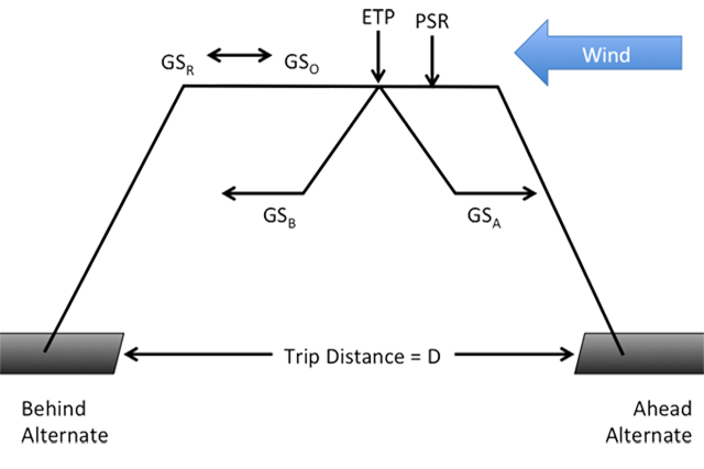
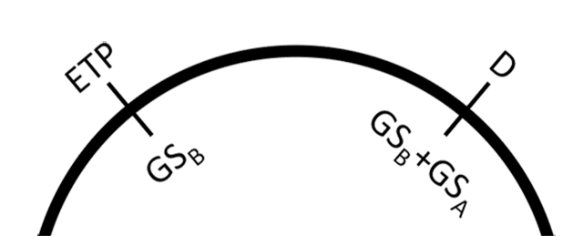
The following formula is used to calculate the ground distance from the departure airport to ETP:
Where:
D = Total Trip Distance
GSA = Ground speed to continue to "Ahead" airport at altitude to be flown
GSB = Ground speed to return to "Behind" airport at altitude to be flown
A few notes:
- In both the navigator and pilot versions the terms "departure" and "destination" are used when in fact they should refer to the alternate airports "ahead" and "behind." You will seldom opt return to your departure point or continue to your destination, though it could happen. Regardless, you will often see "GSR" to denote your groundspeed while returning and "GSC" to denote your groundspeed while continuing.
- The terms GSO and GSR are for the Point of Safe Return (PSR), which is sometimes called the "Point of No Return" (PNR).
More about that: Point of Safe Return.
In our example flight from KBED to LSGG we have plotted one equal time point around 37° West:
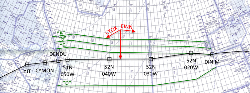
Example Plotting Chart
The single ETP actually reflects three equal time point situations, as covered next.
3
ETP types
Equal Time Points provide pilots with decision making aids in the event the airplane needs to proceed to a landing airport as soon as possible. An ETP is a geographic location along the route of flight where the time to return to an airport behind the aircraft is equal to the time to proceed to an airport in front of the aircraft.
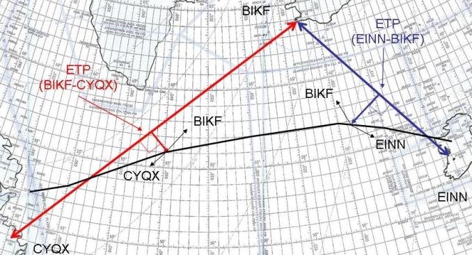
For some routes, a series of ETP location sets may be called for. In the example problem, ETPs between EINN/BIKF and BIKF/CYQX are used. In the event of a problem before the EINN/BIKF ETP, the airplane would turn back to EINN. Beyond this point and before the BIKF/EINN ETP, the airplane would turn north to BIKF. Following this point, a diversion to CYQX would be called for.
At least three types of ETPs should be considered for each location set to cover the following three contingencies:
- Loss of Engine ETP - In the event of an engine loss, drift down procedures are normally used and the airplane may be required to turn to either Loss of Engine ETP.
- Loss of Level ETP - In the event of the loss of pressurization or other problem requiring a rapid descent without an engine loss, the airplane may be required to turn to either Loss of Level ETP. Most flight planning programs compute a rapid descent to 10,000 or 15,000 feet, depending on user preferences. A descent to 10,000 feet permits all occupants to breathe without the use of supplemental oxygen. A descent to 15,000 feet permits passengers to breathe without the use of supplemental oxygen, requires the flight crew to remain on supplemental oxygen, but provides greater endurance.
- Maintain Level ETP - In the event of a need to land as soon as possible without the need to descend, such as a medical emergency, the airplane may be required to turn to either Maintain Level ETP.
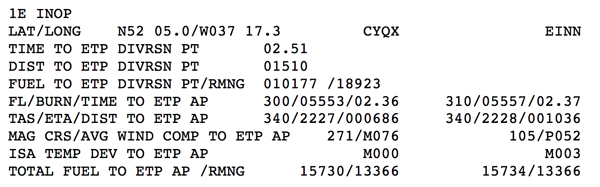
Loss of Engine ETP Example
This ETP can have other names, "1E INOP" in the example shown, but normally means you have lost an engine and must descend and slow down.
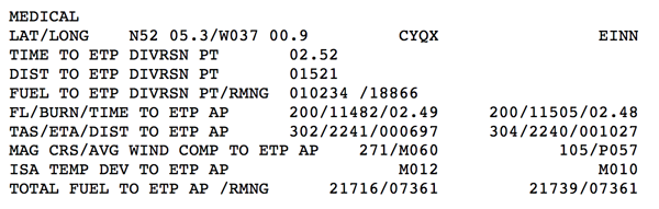
In our example this ETP occurs at N52°05.0' / W037°17.3' which is 1,510 nm along the route of flight from the takeoff point. (This is a useless number when talking ETPs, but four lines later we see the ETP is 686 nm from CYQX.) In the event of an engine loss, the fuel and time are based on descending to FL 300 after reversing course to CYQX or FL 310 pressing forward to EINN. In either case, it will take around 2 hours 36 or 37 minutes at the recommended engine out speed.
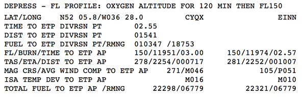
Loss of Level ETP Example
This ETP can also be called "Depressurization" or some variation leading to the idea the airplane must descend.
In our example this ETP occurs just after the Engine-Out ETP, at 1,541 nm along the route of flight from our takeoff point. In the event of loss of pressurization, the aircraft would descend to 15,000' and either turn back or continue east. In either case, it will take around 3 hours at the recommended speed.
Maintain Level ETP Example
This ETP can also be called "Medical" or some variation leading to the idea the airplane divert but not need to descend or decelerate. But some vendors do select what appears to be an arbitrary descent and you may need to request a change from your vendor or compute your own.
In our example the vendor decided a medical ETP requires a descent to FL 200 to make the ETP about the same as what they call the 1E INOP (Loss of Engine) and DEPRESS (Loss of Level) ETPs. This makes flight planning and plotting easier but it is not entirely accurate. Fortunately, with the information they've given us, we can come up with a better answer.
See Computing ETPs / Manually, below.
Selecting ETP Airports
- The oceanic or remote area route of flight should be examined and suitable diversion airports identified based on aircraft requirements, airport capability, and weather. The airport must meet the weather requirements for filing as an alternate and if operating under 14 CFR 135, the aircraft must have the performance to fly en route and hold at least 1,500 feet above all obstacles. [14 CFR 135.381]
- Multiple ETP location sets may be advantageous when the route of flight is near multiple airport options.
If using a computerized flight planning service, always look at the selected ETP airports with a eye towards judging its common sense. The flight planner may have made the airport selections prior to a significant change in winds and it may become obvious the selected airports are no longer viable. You may also receive a routing change that negates the previously selected ETP airports.
4
Computing ETPs
Computer flight plans
Maintain Level ETP Example
Computer ETP Computations are generally superior to manually calculated ETPs because they consider a greater number of wind points and will yield more accurate ETPs. But, as we've seen with this vendor's "DIST TO ETP DIVRSN PT," you need to carefully consider what the data means before making any assumptions.
In our example KBED - KLSGG flight plan, we elected to plot the Maintain Level ETP because it was in the middle. Our flight planning service tells us this ETP occurs 1,521 nm from our departure airport, but more importantly 697 from out "behind" airport, CYQX. The TAS going forward or back are very close but the distance covered is dramatically different because of the 62 knot wind from the west.
Manually
As shown above, ETPs can be computed manually if the ground speed ahead and behind are known. To manually calculate an ETP:
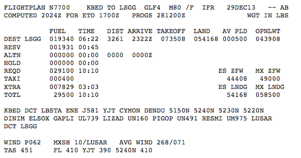
Flight Plan Example, Top Information
All you really need is the wind factor, TAS, and distance between the behind and ahead airports. Remember that GSB = TAS + Wind and GSA = TAS + Wind, and the wind factor is positive if behind you and negative if in front of you.
From our plotting chart we see D = 1722
From our flight plan we see the TAS = 451 and the average wind factor is P062. This could be wildly inaccurate for the pertinent portion of the flight so it pays to scan the oceanic portion to make sure.
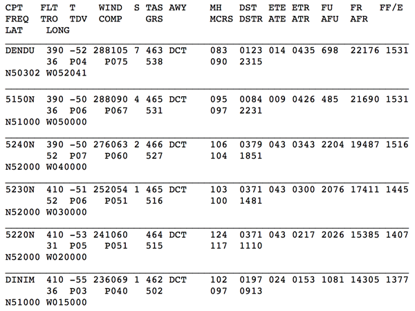
Flight Plan Example, Oceanic Legs
The oceanic legs reveal wind factors of P075, P067, P060, P051, P051, and P040. Rather than use a wind factor of 62 throughout, as the flight plan would suggest, we'll use P067 for our return scenario and P051 for the continue option:
- GSB = TAS + WF = 451 + (-67) = 384
- GSA = TAS + WF = 451 + (+51) = 502
Therefore:
Our manually computed ETP is 50 nm further east than the computerized version because the vendor selected a descent to lower the TAS in an attempt to make the three provided ETPs about the same. If your decision is based on really staying at flight level, the actual ETP is the one we computed, 50 nm east.
5
Circular slide rule
ETP With a Circular Slide Rule
With a circular slide rule, place the Total Distance (D) on the outer scale opposite the added groundspeeds (GSB + GSA), and place the sliding index over the return groundspeed (GSB) on the inner scale. The ETP will appear on the outer scale under the sliding index:
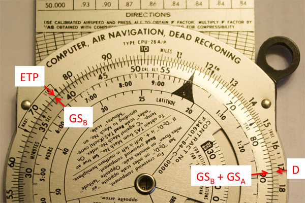
ETP With a Circular Slide Rule Example
The technique works but it introduces an opportunity for error and has been relegated to the "You can, but why would you?" category.
6
Three airport example
There are times when a third airport may become advantageous. (This occurs frequently in the North Atlantic when the route of flight is near Iceland.) For this example, we will compute only the Maintain Level ETP between EINN-BIKF and BIKF-CYQX to illustrate the positioning of the ETP on the route of flight. (The process of checking the Loss of Level and Loss of Engine ETPs is the same, using the appropriate groundspeeds for those scenarios.)
- Maintain Level ETP (EINN-BIKF). Using our FMS or by measuring the distance on the plotting chart, we see the distance between EINN and BIKF is 798 nm. For the example our True Airspeed is 492 knots but this time our winds will be out of the west at 20 knots.
- Maintain Level ETP (BIKF-CYQX). Using our FMS or by measuring the distance on the plotting chart, we see the distance between BIKF and CYQX is 1367 nm. Once again our True Airspeed is 492 knots but this time our winds will be out of the west at 10 knots.
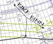
- Each of these points are plotted on straight lines between airports. A line is then drawn from these points at a right angle towards the actual aircraft route of flight. Where the lines intersect are the appropriate equal time points:
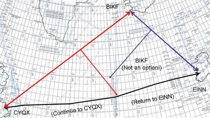
- In this example, the emergency options will be to turn back to EINN before the first ETP, to divert north to BIKF between the first and second ETPs, and finally to press on to CYQX after the second ETP.
- If the winds were especially strong up north and the route of flight was further south, we could see a case where it is never advantageous to proceed to one of the three ETP choices. In the example shown below, the flight time to either EINN or CYQX is always shorter than BIKF:
ETP (EINN-BIKF) = (798 × 512) / (512 + 472) = 415 nm from EINN
ETP (BIKF-CYQX) = (1367 × 502) / (502 + 482) = 697 nm from BIKF
7
Plot ETPs
If a plotting chart is required the ETPs should be noted along the route of flight. More about: Plotting.
A perpendicular line pointing to the route and arrows pointing to the ETP airports will allow rapid and easy identification of a course of action if a diversion decision becomes necessary.
If a plotting chart is not used, another means of identifying the ETP should be employed. A pencil mark on the en route chart is normally sufficient. Some FMS units allow an electronic display of a non-flight plan point that allows easy reference.
You should not enter ETPs in the active route of the LRNS because additional waypoints, even if along the route, can produce nuisance out-of-conformance alerts on ground-based monitoring systems. Also, crew misunderstanding about these additional waypoints has occasionally led to pilot deviations from the cleared route.
Source: AC 91-70B, ¶D.2.1.4.4
CAUTION: Do not enter the ETP into the FMS as a waypoint. ADS-C will generate a message in response to an event contract and that will cause ATC to think you are doing something wrong. Even if you don't have ADS-C it is considered best practices to keep any extraneous points out of the FMS for the sake of timing and fuel planning.
There is a lot of misinformation about why you should never insert an ETP into an FMS, and most of it is wrong. I have been taught since day one that inserting an ETP between two points of a great circle will change that great circle. That isn't true, it doesn't change the course, that is a myth: The Great Circle ETP Myth. The primary reason in a modern cockpit is that the adding the ETP will generate an event contract under ADS-C. More about this: ADS-C / Event Contracts. But even in a older technology cockpit you should still leave the ETP out of your FMS because it changes the distances for your cross check of what is really happening versus what should be happening.
References
(Source material)
Advisory Circular 91-70B, Oceanic and International Operations, 10/4/16, U.S. Department of Transportation
Air Force Manual (AFM) 51-40, Air Navigation, Flying Training, 1 July 1973
Gulfstream G450 Performance Handbook, GAC-AC-G450-OPS-0003, Revision 20, November 30, 2011
Please note: Gulfstream Aerospace Corporation has no affiliation or connection whatsoever with this website, and Gulfstream does not review, endorse, or approve any of the content included on the site. As a result, Gulfstream is not responsible or liable for your use of any materials or information obtained from this site.