Instrument pilots used to need a keen understanding of aircraft turn performance to negotiate procedure turns, circling approaches, or to simply fly a proper course intercepts. These days, of course, flight directors seem to manage all of that for us. Except when they don't.
— James Albright

Updated:
2021-12-01
Understanding altitude and speed effects on aircraft turn performance can make your life easier when it comes to:
If you are flying a high technology airplane you can employ these techniques graphically with ease. A G650, for example, allows you to constrain turn speeds and see visually the impact on a turning SID. But even if your aircraft avionics don't give you this capability, seeing the technique in action will help visualize how these techniques can help you remain within charted airspace.
1
Theory
Dole, pg. 188
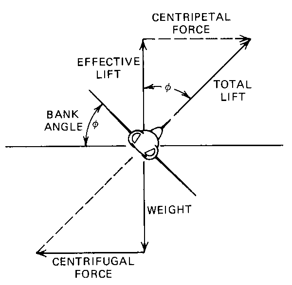
One of the early lessons in high speed military aviation is that aircraft do not bank around turns, they pull their way around the turn. It is the aerodynamic force of the wing that causes the airplane to turn in level flight. That is true of any airplane, but it is an inescapable fact in an airplane that enters the traffic pattern at 300 knots.
Recall from Newton's Second Law of Motion that an unbalanced force will accelerate a body in the direction of the force. The aerodynamic force that is tilted into the turn is what is called centripetal force. The mass of the aircraft resists that turn into the turn with a force away from the turn known as centrifugal force. As long as the aircraft is in coordinated flight, these forces will be balanced.
The key takeaway for a pilot who doesn't spend much time thinking about G-forces around a turn is that the airplane must have back pressure in the pitch mode to turn in level flight.
We can solve for the angle θ with a little trigonometry using the figure shown:
The load factor on an aircraft is defined:
With a little substitution:
Dole, pg. 189
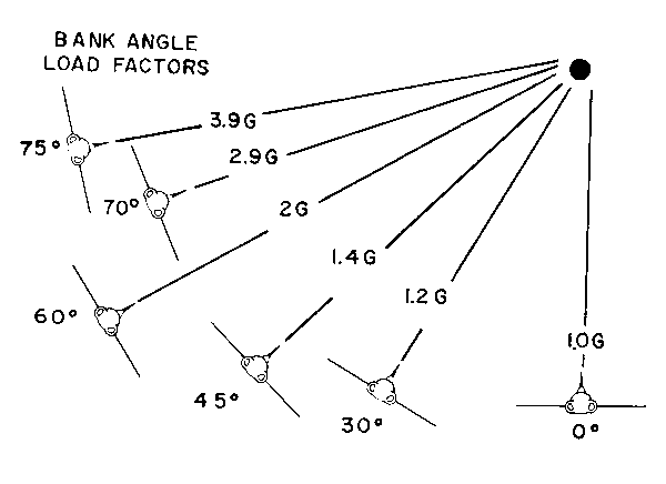
From this formula we can derive load factors for various bank angles in level, coordinated flight.
2
Exactly
Turn Radius
Dole, pg. 188
As we saw in the theory section, the force turning the aircraft is its centripetal force. Using the diagram, we see that:
Newton's Second Law of Motion also tells us that F = ma, so we can say:
Where r is the radius of turn.
Equating the two equations:
Looking again at the figure, we see that:
Dividing the sine equation by the cosine equation gives us:
Solving for r:
Substituting g = 32 ft/sec2 and converting all figures to knots and degrees yields an equation for radius of turn in feet from TAS and degrees bank.
Where V = velocity in knots TAS and φ = bank angle in degrees.
The horizontal component of lift will equal the centrifugal force of steady, turning flight. This fact allows development of the following relationships of turning performance:
turn radius
where:
r = turn radius, ft
V = velocity, knots (TAS)
θ = bank angle, degrees
Source: ATCM 51-3, pg. 178
Doing the math for a 25° bank turn and converting V (in knots) to v (in nautical miles per minute). Notice the upper versus lower cases used to show the different units:
R = radius in nm
r = radius in ft
V = velocity in nm/hr
v = velocity in nm/min
Given:
Then:
And:
And:
If θ = 25
Which is close enough to say:

Turn radius (nautical miles) = (nautical miles per minute)2 / 9
Turn Rate
where:
ROT = rate of turn, degrees per second
V = velocity, knots (TAS)
θ = bank angle, degrees
ATCM 51-3, figure 2.29
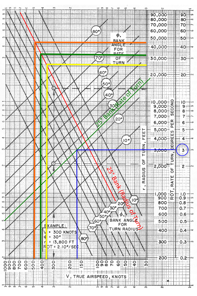
At first examination, you would think figuring turn radius in level flight and at a steady rate should be easy. But it isn't because at the speeds and altitudes we fly, a standard rate turn isn't always possible without a G-suit. The chart shown comes from an Air Force Aerodynamics book and refers to "Steady Rate." That just means the turn is being executed without variation in G-forces. The trouble with a standard rate turn is that it requires a varying bank angle with true airspeed. Since we are not turning for the sake of getting on another airplane's six, we can simplify things by agreeing on a few rules on how we are going to turn the airplane:
- A standard rate turn is defined as a 360° turn completed in 2 minutes, which comes to 360 / (2)(60) = 3° / second.
- Most transport category aircraft limit instrument turn bank angles to 25°, though some use as much as 30° of bank. The green line on the chart is drawn at 25° of bank for the rate of turn scale which is furthest right. As can be seen, a standard rate turn will require more than 25° of bank when true air speed exceeds 170 knots.
- Radius of Turn (Standard Rate, below 170 knots TAS) — As a rule of thumb, radius of turn can be approximated by diving the number of miles per minute true airspeed by three.
- Radius of Turn (25° bank, above 170 knots TAS) — As a rule of thumb, radius of turn can be approximated by squaring the miles per minute and dividing by 9.
The turn radius of a standard rate turn at 120 knots is 2/3 nm
The turn radius of a standard rate turn at 150 knots is 0.8 nm
The turn radius of a 25° bank turn at 360 knots is 4 nm
The turn radius of a 25° bank turn at 420 knots is 5.4 nm
The turn radius of a 25° bank turn at 450 knots is 6.25 nm
The turn radius of a 25° bank turn at 480 knots is 7.1 nm
3
A good wag
Sometimes a "wag" is as good as a formula
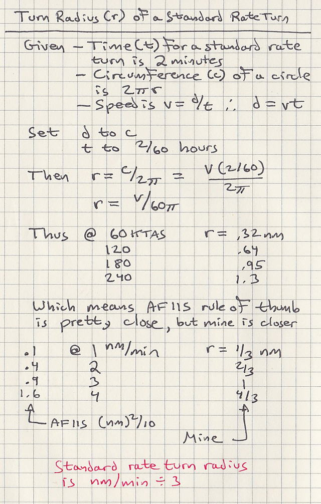
Turn radius notes
These hand-written notes are from about 1985 and failed to consider the limiting bank angle of a standard rate turn. The instrument instructor school tended to ignore the discrepancy: if you can't get the data to agree with the theory, ignore the data. It wasn't until a few years later that I figured out the problem and came up with the alternate theory for higher speeds, shown above.
If you are flying a typical business jet, then most of your circling is done right around 130 knots which is just a little faster than 2 miles per minute. Divide that by three and you get a turn radius of 2/3 nm. That explains why most of us are comfortable flying a traffic pattern with a 1-1/2 mile offset, 2 miles is even better.
A standard rate turn is possible up to 170 knots TAS and has a radius is equal to nm/min divided by 3.
A 25° bank angle turn will be needed above 170 knots TAS and has a radius equal to (nm/min)2 divided by 9.
4
G650 example
Understanding the technology . . .
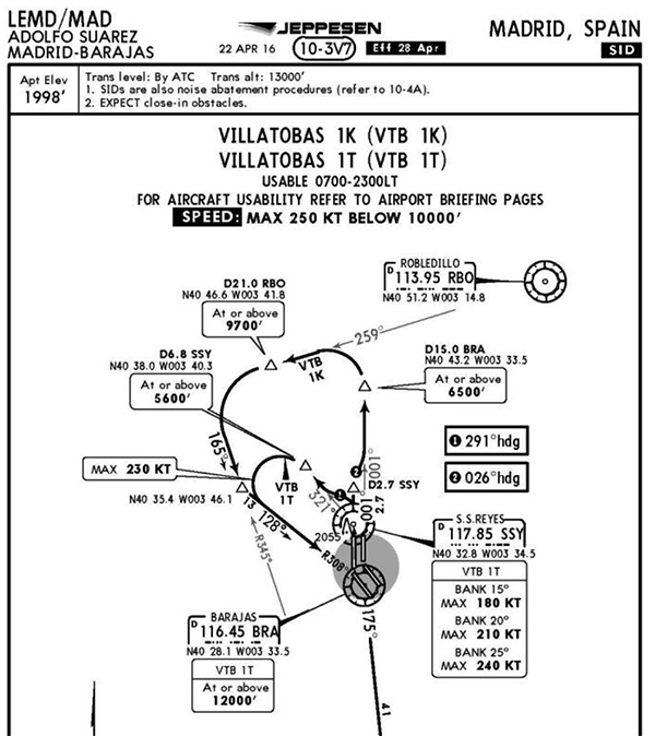
LEMD departure example, figure 1
An example of an Instrument Departure with a small radius turn is presented in Figure 1, which shows the published chart for the Villatobas 1K (VTB 1K) and Villatobas 1T (VTB 1T) at Adolfo Suarez Madrid-Barajas airport (LEMD).
Source: G650-OMS-06, pg. 2
The G650 FMS will default to 200 KCAS within 4 NM of the runway and then to 250 KCAS while below 10,000' MSL. But will the aircraft's turn radius be too great at this speed to maintain the ground track?
The required turn diameter appears to be about 5 NM, just eyeballing the chart. Assuming our TAS increases as we climb, we can estimate our turn radius from the chart above using 300 average TAS and 25° bank commanded by the FMS to be about 18,000' for a turn diameter of (2)(18,000)/(6,076) = 6 NM, too much.
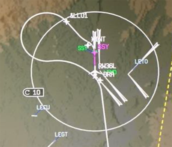
LEMD departure example, figure 2
Figure 2 shows the FMS computed path for the Villatobas 1T (VTB 1T) instrument departure from Runway 36L at LEMD. The default departure speed limits of 200 KCAS (below 2500 ft AGL and within 4 NM of departure airport), 250 KCAS below 10,000 ft (referenced to the altimeter), and a Climb speed of 320/.87M were entered on the Performance Initialization menus. Note the wide turn from &LL01; (D6.8 SSY on Figure 1) toward BRA, and the 230 KCAS speed at *INT, which is only approximately 2.7 NM from the departure end of Runway 36L. This depiction on the I-NAV MAP is with the airplane on the ground before takeoff, providing a clear depiction of the computed route of flight the airplane will follow on takeoff. This provides the crew situation awareness during their preflight checks and should alert them that an adjustment is required to preclude deviating from the Instrument Departure routing.
Source: G650-OMS-06, pg. 2
The G650 FMS draws us a picture telling us what we computed with the chart, our turn radius will exceed the charted course if we fail to constrain the FMS speed targets.
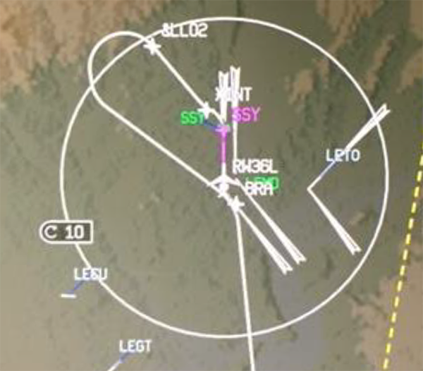
LEMD departure example, figure 3
Reducing the airplane radius of turn is easily accomplished by reducing the airplane departure speed. Prior to takeoff, insert a speed constraint in the Active Flight Plan on the waypoint down path of the route segment that includes the small radius turn. In the example scenario, place the speed constraint on the BRA waypoint. Doing so applies the speed constraint to the BRA waypoint and all waypoints preceding BRA. Confirm that the speed constraint is applied to all previous waypoints because it may not initially supersede a speed retrieved from the database, possibly requiring an additional speed constraint entry on the waypoint(s) already having a speed retrieved from the database. After entering the speed constraint into the Active Flight Plan, it may require 10 to 15 seconds for the FMS to completely recalculate the route and depict it on the I-NAV MAP (Figure 3).
If the speed constraint that is necessary to satisfy the Instrument Departure route is uncharacteristically slow, it may be necessary to perform the small radius turn with the flaps not at the fully retracted position in order to retain speed margin above VMIN.
Source: G650-OMS-06, pg. 5
Reducing our speed to the 230 KTS restriction appears to help. But we still aren't sure exactly. With or without this technology, being able to estimate your turn radius tells you that this departure cannot be flown on a normal speed schedule. With the G650 you can further reduce your speed and see graphically at what speed you will be okay. Without this technology, I would elect to fly the procedure at takeoff flap setting and V2+10, just to be sure.
References
(Source material)
Air Training Command Manual 51-3, Aerodynamics for Pilots, 15 November 1963
Air Force Manual (AFM) 51-37, Instrument Flying, 1 December 1976
Dole, Charles E., Flight Theory and Aerodynamics, 1981, John Wiley & Sons, Inc, New York, NY, 1981.
G650 Operating Manual Supplement 06, Instrument Departures with Small Turn Radius Turns, G650-OMS-06, Basic Issue, August 29, 2016
Please note: Gulfstream Aerospace Corporation has no affiliation or connection whatsoever with this website, and Gulfstream does not review, endorse, or approve any of the content included on the site. As a result, Gulfstream is not responsible or liable for your use of any materials or information obtained from this site.